OVERVIEW
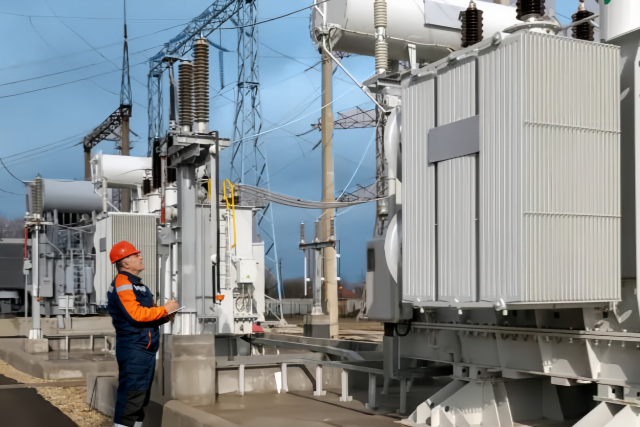
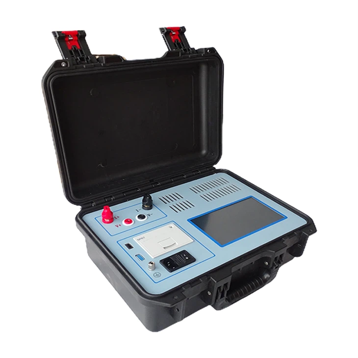
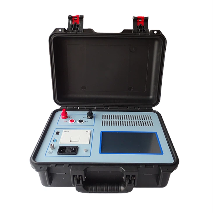
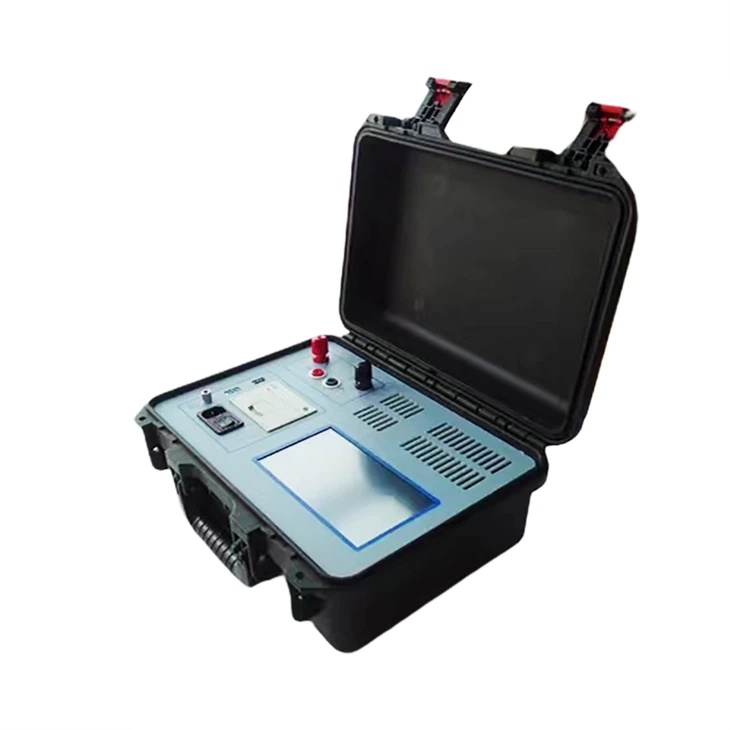
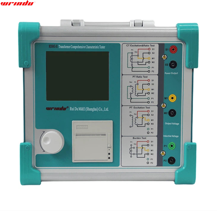
Electricity equipment, ground lead, and reliable connection with ground networks are the basis for ensuring the safe operation of the equipment. The grounding is a key channel for connecting power equipment and the ground network. When the equipment runs for a long time, humidity easily affects it, causing rust or even breaking at the connection. In this way, the resistance of the connection point of the main connection with the main connection of the ground does not comply with the requirements of the power regulations. Still, the hidden safety hazards will be buried for the equipment operation. In severe cases, the equipment will also lose ground protection. Given this, our company has developed a highly automated, portable continuity tester for grounding specifically to measure the pitch resistance value between the power equipment in the substation in the substation to help ensure the safe and stable operation of the power system.
CHARACTERISTIC
1. Using high-performance single-chip microcomputer control can achieve the intelligence of the test process.
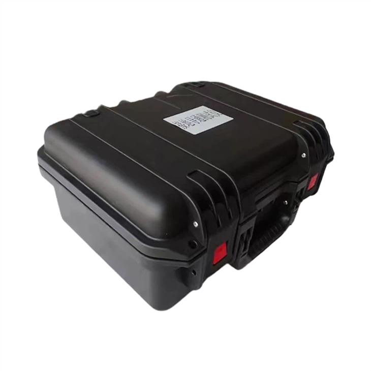
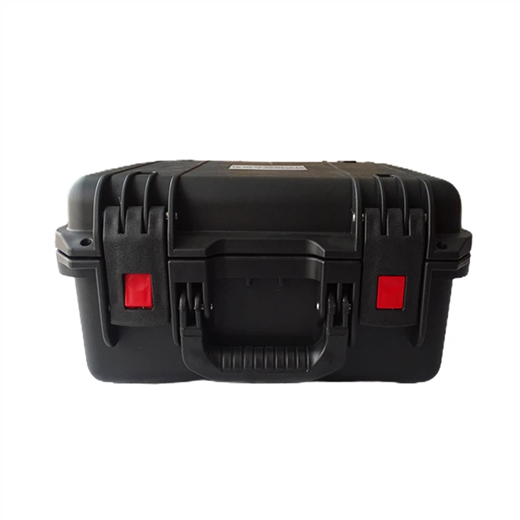
2. The continuity tester for grounding design is compact and light, easy to carry and operate.
3. High test accuracy, fast speed, good repeatability, clear and intuitive reading.
For more information ground resistance test equipment, please click More.
To request the latest quotes, please click to Contact Us.
FAQ
Q: What is the maximum ground resistance to earth for ground rods and fields?
A: As per the National Electrical Code (NEC) in the U.S., ground rods’ resistance should not exceed 25 ohms. If it does, NEC advises using two or more rods connected in parallel, spaced at least six feet apart. Adhering to these guidelines is crucial for effective grounding, electrical safety, and compliance with local codes.
Q: What should the earth’s resistance not exceed?
A: The combined earth resistance at an auxiliary transformer station should not exceed 10 ohms, with a single earth electrode generally considered sufficient for the station’s grounding. This is essential for ensuring safety and minimizing the risk of electrical faults.
Q: What is the maximum allowable resistance for the earth continuity test?
A: Certainly! In the context of earthing continuity, it is advisable to disconnect any earth bond conductor where practical. The goal is to measure the resistance with a maximum allowable limit of 0.5 milliohms (mΩ). This ensures a low-resistance path for fault currents, promoting effective grounding and electrical safety.

