OVERVIEW
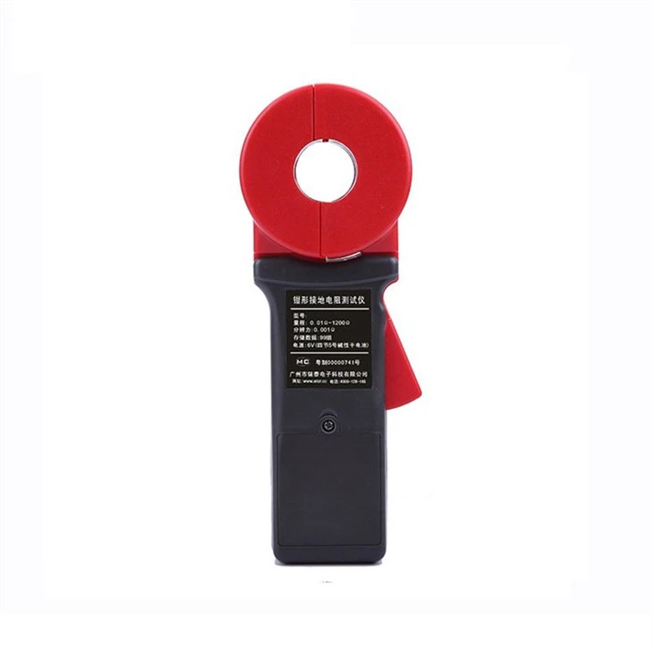
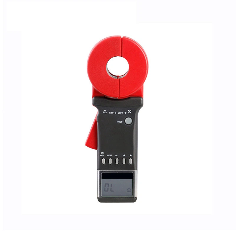
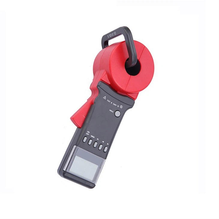
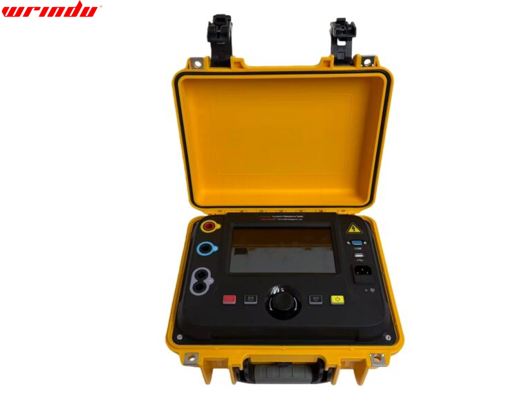
The earth resistance clamp tester is a comprehensive upgrade of the old model, with many vital improvements. In the startup phase, the problem of the old equipment taking too long to start the self-test is solved. It can be started with one button, and the test state can be quickly entered. The traditional relay self-test mode is abandoned at the technical level, and advanced algorithms and digital integrated processing technology are used to improve the test accuracy and stability effectively. In terms of design, the new model is more lightweight and portable, which fits the use characteristics of handheld devices. The latest appearance and intuitive six-key operation interface make it easy for first-time users to operate. The earth resistance clamp meter has a new sound and light alarm function. When an abnormality is detected, an alarm will prompt potential problems. It can also identify interference signals and use sound to inform about external interference. The measurement range is extended from 0.01Ω to 1200Ω, which significantly broadens the scope of application. Its maximum startup and working currents are controlled within 50mA, the energy consumption is reduced considerably, and 99 data sets can be stored. This clamp-on ground resistance meter is widely used to measure ground resistance and loop resistance in many fields, such as power, telecommunications, meteorology, oil fields, construction and industrial electrical equipment. The measurement can be completed for loop grounding systems without disconnecting the grounding lead and auxiliary grounding electrode, which is safe and efficient. Because it can measure the sum of the ground body resistance and the grounding lead resistance, it can detect grounding faults that are difficult to detect with traditional methods in unique scenarios.
CHARACTERISTIC
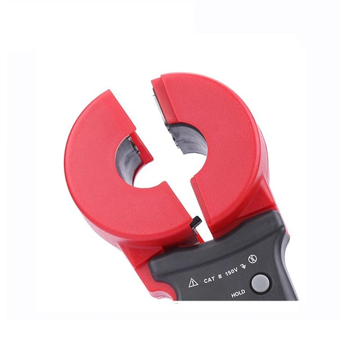
- 1. A significant ground resistance test technology breakthrough, the non-contact measurement method ensures operational safety.
- 2. When using this instrument for measurement, there is no need to disconnect the grounding lead or set up auxiliary grounding electrodes for grounding systems with loops, saving time and labour costs.
- 3. The earth resistance clamp tester can detect ground faults that are difficult to detect with traditional methods and is suitable for occasions where conventional methods cannot be used for measurement.
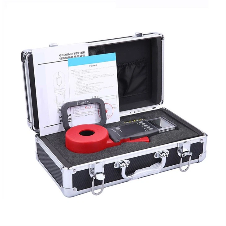
- 4. The instrument has sound and light alarm functions and data storage and retention.
For more information about clamp-on ground resistance test equipment, please click More.
To request the latest quotes, please click Contact Us.
FAQ
Q: Can a clamp meter measure earth resistance
A: Traditional clamp meters can’t measure earth resistance, as they’re designed for current conductors. Earth Resistance Clamp Testers or Ground Resistance Testers, with specialized probes or clamps, are used for this purpose. They assess grounding system effectiveness and ensure safety in electrical installations.
Q: How do you use a clamp-on-earth resistance tester?
A:
1. Prepare & Calibrate:
– Ensure the clamp-on earth resistance tester is calibrated.
2. Select Mode:
– Set to earth resistance measurement mode.
3. Place Clamp:
– Securely attach around the grounding conductor.
4. Take Reading:
– Activate for earth resistance value.
5. Interpret & Record:
– Compare with standards and document results.
Q: How do you test earthing resistance?
A: Four earth resistance testing methods include:
1. Soil Resistivity: Measures soil’s resistance using stakes.
2. Fall-of-Potential: Uses stakes to gauge earth resistance.
3. Selective: Combines 1 clamp and stakes for testing.
4. Stateless: Utilizes 2 clamps only for resistance assessment.
APPLICATION


