Wrindu

Double Clamp Multifunctional Earth Tester

The Double Clamp Ground Resistance Tester measures earth resistance, soil resistivity, voltage, leakage, and AC with a large clamp design for significant grounding leads.
Models: RD3031E, RD3032E

Related Products

OVERVIEW


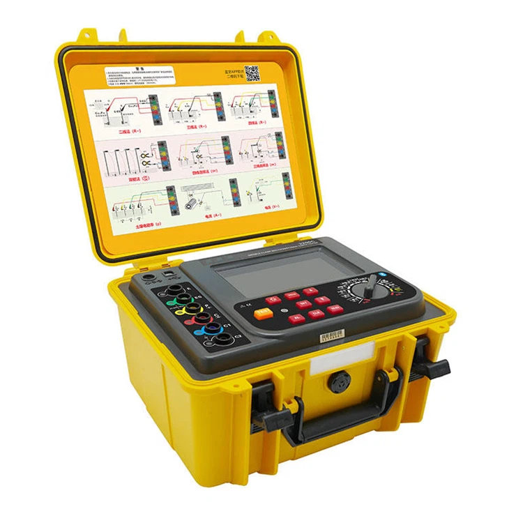
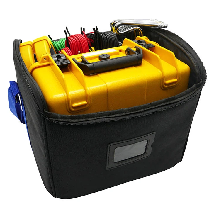
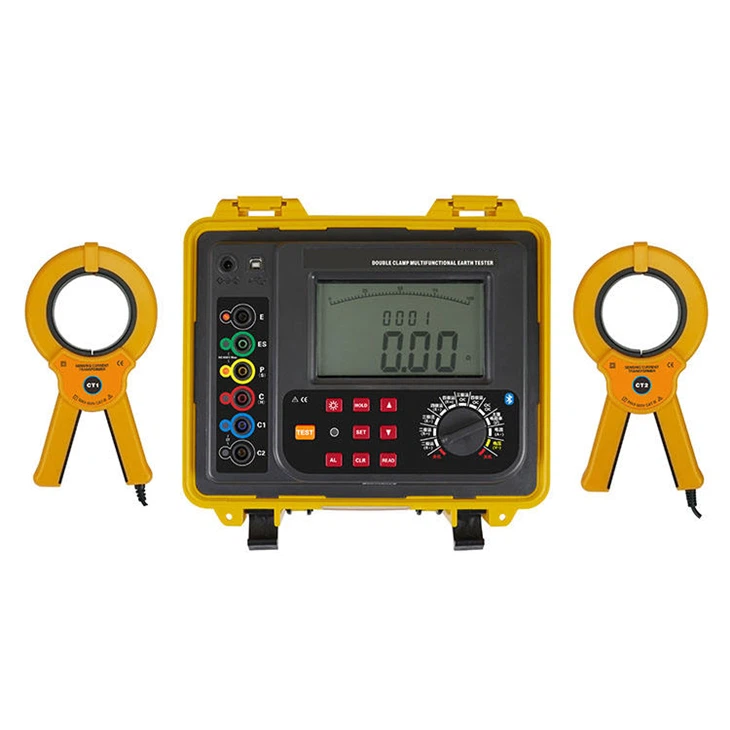
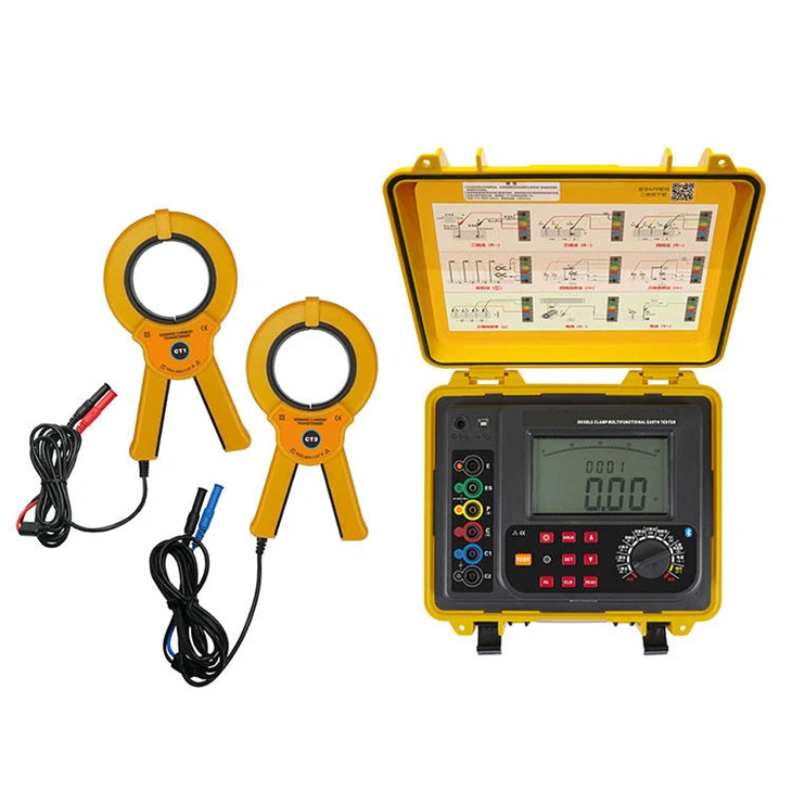
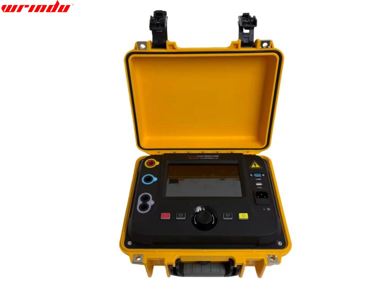
A double – clamp ground resistance tester combines multiple functions. It can measure ground resistance, soil resistivity, ground voltage, ground – wire leakage current, and alternating current (AC). It supports a variety of measurement methods, such as the precision 4-line method, 3-line method, simple 2-line method, selection method, and dual clamp method, which can flexibly cope with various measurement needs. Its large-diameter current clamp design can directly measure the ground resistance value of complex grounding structures such as the under-line ground system, accurately testing single-point and mesh grounding. Convenient. The test instrument uses FFT (Four -Fourier Transformation) technology and AFC (automatic frequency control) technology to ensure high accuracy, stable and reliable measurement results. The shell adopts a solid and durable waterproof protective box, which is anti-collision, falling, and waterproof (the protective grade of the lid is up to IP65), which is suitable for harsh environments such as outdoor construction sites.


CHARACTERISTIC


  • 1. It is equipped with an LCD with backlight and stick – diagram instructions.
  • 2. Reserve up to 2,000 sets of data.
  • 3.It has alarm instructions and automatic shutdown functions.
  • 4. The double clamp ground resistance tester supports the reading and review of historical data.


For more information about clamp-type ground resistance testers, please click More.
To request the latest quotes, please click Contact Us.


FAQ


Q: How do you measure ground resistance with a clamp meter?

A:

1. Get a Grounding Clamp Meter:
Ensure it has a “ground resistance” function.

2. Prepare and Isolate:
Clean the area, disconnect the grounding, and zero the clamp.

3. Position and Measure:
Clamp around the electrode, and measure the current.

4. Calculate Resistance:
Use Ohm’s Law or check the meter reading.

5. Interpret Results:
Compared with standards, lower values are better. Always follow safety guidelines.


Q: What is the theory of clamp-on ground resistance tester?

A: A clamp-on ground resistance tester employs inductive coupling, detecting the magnetic field induced by ground current. The clamp sensor analyzes this field to calculate ground resistance, providing efficient and non-intrusive testing without direct contact with the ground.


Q: What are the three most common methods of determining ground resistance?

A:

1. Fall of Potential (3-point) Method:

Measures voltage drop between a current injection electrode and a distant ground electrode.
2. Wenner 4-point Method:

Utilizes four equally spaced electrodes to assess ground resistance.
3. Clamp-On Method:

A clamp meter measures the magnetic field around the grounding conductor, determining resistance without ground contact.

Technical Parameters

PictureTwo Clamp Ground Resistance Measurement DeviceDual Clamp Ground Resistance Meter For Industrial Use
ModelRD3031ERD3032E
Power SupplyPower Supply: DC 9V, 6PCS of 1.5V LR14 alkaline dry cells; Standby Time: 300 hoursDC 7.4V 2600mAh rechargeable lithium battery, full of about 8.4V
Data UploadRS232 interface, storage data can be uploaded to a computer, saved, or printed.With a USB interface, software monitoring, and storage data can be uploaded to a computer, saved, and printed.
Data ModelAverage value, maximum, minimum value
Short-circuit Test CurrentAC 20mA maxAC 100mA max
Battery VoltageWhen the battery voltage decreases to around 7.5V, the tester will display the low – battery symbol ‘ ‘, and remind the user to replace the batteryWhen the battery voltage decreases to around 7.2V±0.1V, the tester will display the low – battery symbol and remind the user to charge.
Protection LevelIP65 (close the case)
FunctionDescription
LCD Size124mm x 67mm (with backlight)
Data Storage2000 groups
Automatic Shut DownAutomatically shut down after 15 minutes start up
Power ConsumptionTurn on the backlight: 45mA Max
Turn off the backlight: 25mA Max
Measurement: 100mA Max (Backlight shut off)
Working Temperature & Humidity-10℃ ~ 40℃, below 80% RH
Storage temperature & humidity-20℃ ~ 60℃, below 70% RH
Clamp Caliber68 mm
Measuring Method2/3/4 – pole Measurement Method: Pole – changing method; Maximum Measurement Current: 20mA
Selection measurement method: Change-pole method, measurement current 20mA Max.
Double clamp measurement method: Non-connect mutual inductance method, measurement current 1mA Max.
Soil Resistivity: 4-pole measurement (Wenner method)
AC: Mutual inductance method (clamp)
Earth Voltage: Average rectification (between P(S)-ES)
Test Frequency128Hz/111Hz/105Hz/94Hz (AFC)
line resistance checkAutomatic calibration
Measuring RateAC: about 2 times/second
Earth Voltage: about 2 times/second
Earth resistance, soil resistivity: about 7 seconds/time
Measuring TimesOver 5000 times (Short-circuit test, interval time should be at least 30 seconds)
Open-circuit Test VoltageAC 40V max
Test Voltage WaveSine wave
Electrode Distance Range1m ~ 100m
Line VoltageMeasurement below AC 600V
Data HoldData hold function: “HOLD” symbol display
Data AccessData read function: “READ” symbol display
Overflow DisplayExceed measuring range overflow function: “OL” symbol display
Auxiliary Grounding TestWith auxiliary grounding resistance test function, 0.00KΩ ~ 30kΩ (100R+rC<50kΩ, 100R+rP<50kΩ)
Interference TestAutomatic identification of interference signals, “NOISE” symbol indication when the interference voltage is higher than 5V.
Alarm FunctionMeasuring value exceeds the alarm setting value, will “Toot-toot-toot” alarm hint.
Overload ProtectionMeasure earth resistance: between each interface of E-P, E-E- C, AC 280V/3 seconds
Insulation ResistanceOver 20MΩ (between circuit and outside shell is 500V)
Withstand VoltageAC 3700V/rms. (Between circuit and outside shell)
Electromagnetic FeaturesIEC61010- 4-3, Wireless frequency electromagnetic field ≤1 V/m
Protection TypeIEC61010-1 (CAT Ⅲ 300V, CAT IV 150V, Pollution 2);
IEC61010-031;
IEC61557-1 (Earth resistance);
IEC61557-5 (Soil resistivity);
JJG 366-2004 (Grounding resistance meter).


Measurement Range & Accuracy

ModelRD3031E & RD3032E
Measurement FunctionMeasurement RangeIntrinsic ErrorResolution
2/3/4 pole method measures earth resistance (Re)0.00Ω ~ 29.99Ω± 2% rdg ± 5 dgt0.01Ω
30.0Ω ~ 299.9Ω± 2% rdg ± 3 dgt0.1Ω
300Ω ~ 2999Ω± 2% rdg ± 3 dgt
3.00kΩ ~ 300kΩ± 4% rdg ± 3 dgt10Ω
Selection method measure grounding resistance (Re)0.00Ω ~ 29.99Ω± 2% rdg ± 5 dgt0.01Ω
30.0Ω ~ 299.9Ω± 2% rdg ± 3 dgt0.1Ω
300Ω ~ 3000Ω± 2% rdg ± 3 dgt
The double clamp method measures grounding resistance (Re)0.01Ω ~ 0.99Ω± 10% rdg ± 5 dgt0.01Ω
1.0Ω ~ 29.9Ω0.1Ω
30Ω ~ 100Ω
Soil Resistivity (ρ)0.00Ωm ~ 99.99ΩmAccuracy: Based on the measurement accuracy of R, calculated as ρ = 2πaR (where a ranges from 1m to 100m and π = 3.14)0.01Ωm
100.0Ωm ~ 999.9Ωm0.1Ωm
1000Ωm ~ 9999Ωm1Ωm
10.00kΩm ~ 99.99kΩm10Ωm
100.0kΩm ~ 999.9kΩm100Ωm
1000kΩm ~ 9000kΩm1kΩm
Earth Voltage (50Hz/60Hz)AC 0.0 ~ 100.0V±2% rdg ± 3 dgt0.1V
Alternatingcurrent (50Hz/60Hz)0.0mA ~ 600.0A±2% rdg ± 3 dgt0.01mA

Send Inquiry