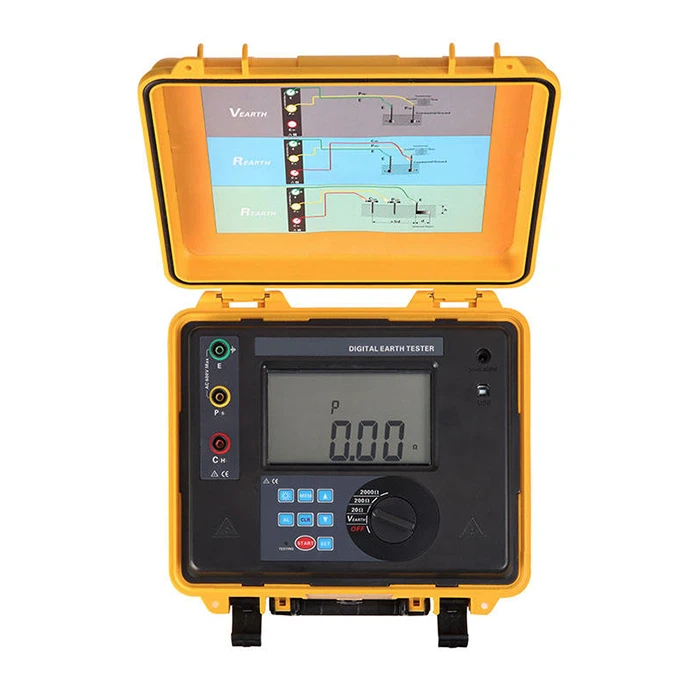
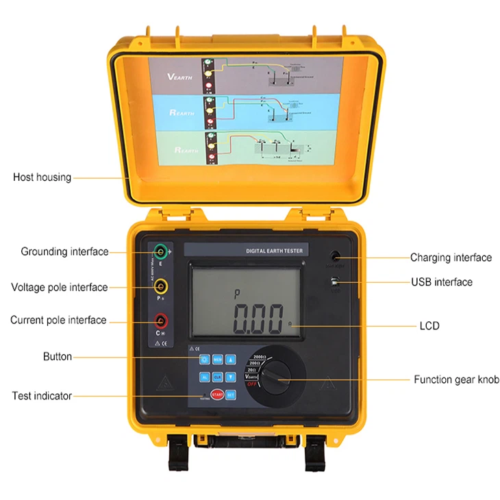
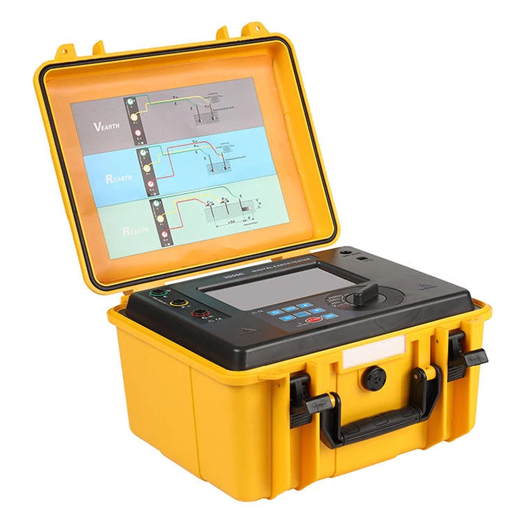
Wrindu

Digital Ground Resistance Tester

The digital ground resistance tester, with 3-wire or 2-wire methods, ensures precision in outdoor measurements. Robust, waterproof (IP65), and suitable for various industries.
Models: RD3011E, RD3012E

Related Products

Wrindu Handheld PD Tester
double-stage-vacuum-transformer-oilb7e1c
图片
transformer-comprehensive-test-benchf7b9e5a1-76f6-4a19-a072-8aadc4aefb21

OVERVIEW


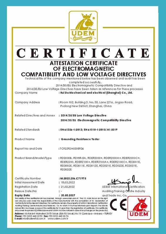
Our company’s digital ground resistance tester is designed for on-site ground resistance measurement. It integrates digital and microprocessing technology and can accurately measure ground resistance using precision 3-wire or simple 2-wire methods. The instrument has excellent wire resistance calibration characteristics, anti-interference solid performance, and excellent environmental adaptability, which effectively guarantees high precision, stability, and reliability in long-term measurement operations. Among them, the unique wire resistance calibration function of the new ground resistance tester shows higher accuracy for on-site low-value ground resistance measurement, effectively avoiding errors caused by changes in wire resistance due to long-term use of the test line and preventing deviations caused by incomplete insertion or poor contact between the test line and the instrument interface, as well as errors caused by users replacing or extending the test line. This product has extensive applications in ground resistance measurement in power, telecommunications, meteorology, construction, lightning protection, and industrial electrical equipment.


CHARACTERISTIC


  • 1. Provides dedicated line resistance calibration function
  • 2. It has an LCD, supports white backlight, and an intuitive bar graph display function.
  • 3. Supports storage of 400 sets of data
  • 4. It can display maximum, minimum, and average values
  • 5. With historical data reading and review function
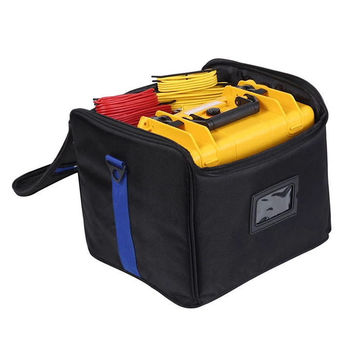
  • 6. The digital ground resistance tester shell adopts a sturdy, waterproof protective box design with anti-collision, anti-fall, and waterproof functions.


For more information about ground resistance testers, please click More.
To request the latest quotes, please click Contact Us.


FAQ


Q: How do you test earth ground resistance?

A:

1. Fall-of-Potential Test:

Procedure: Equilateral triangle stakes, measure voltage drop.
Calculation: R = Voltage Drop / Current.

2. Four-Pole Testing:

Enhancement: Adds an extra potential electrode.

3. Clamp-On Testing:

Tool: Specialized clamp-on tester.
Method: Measures magnetic field.

4. Wenner 4-Wire Method:

Setup: Four equally spaced electrodes.

5. Soil Resistivity Testing:

Objective: Evaluate soil resistivity for grounding system design.


Q: What is the earth resistance tester?

A: A digital ground resistance tester is a tool that measures how well electrical grounding systems can dissipate currents into the ground, ensuring safety and preventing electrical hazards. It typically uses the fall-of-potential method, involves multiple electrodes, and is portable and digital for accurate readings. Regular testing is essential for maintaining a reliable grounding system.


Q: What is an acceptable earth ground resistance value?

A: The acceptable earth ground resistance value isn’t universally standardized. Generally:
– NFPA and IEEE recommend aiming for 5.0 ohms or less.
– NEC suggests ensuring system impedance to ground is below 25 ohms (as per NEC 250.56).
Specific industry guidelines and local regulations might influence the acceptable resistance value.

Technical Parameters

Picture Digital Earth Resistance Analyzer Digital Earth Ground Resistance Tester Meter
Model RD3011E RD3012E
Function Measurement of earth resistance, voltage to earth Measurement of earth resistance, voltage to earth, low-value resistance
Power Supply DC 9V Alkaline dry cell LR14 1.5V×6pcs DC 7.4V 2600mAh rechargeable lithium battery, full of about 8.4V
Test Frequency 128Hz 128Hz/ 111Hz/ 105Hz/ 94Hz (AFC)
Meter Dimension 215mm (L) × 178mm (W) × 83mm (H) 280mm (L) × 260mm (W) × 160mm (H)
Simple Test Wire Red 1.6m 2 wires: each for red 1.6m and black 1.6m
Communication Interface With a USB interface and software monitoring, storage data can be uploaded to a computer, saved, or printed.
Communication Wire One piece of USB communication wire, wire length 1.5m.
Auto-shut off Automatically shut down after 10 minutes.
Battery Voltage While the battery voltage decreases to around 7.8V±0.1V, will display the battery voltage low symbol, and remind you to charge the battery. When the battery voltage decreases to around 7.2V±0.1V, will display the battery voltage low symbol, and remind you to charge the battery.
Alarm Function Measuring value exceeds the alarm setting value, the LCD flashes display the alarm symbol. Measuring value exceeds the alarm setting value, will “Toot-toot-toot” alarm hint.
Weight Tester: 1.325kg Tester: 4.73kg
Test wires: 0.847kg (including the simple test wires)
Auxiliary Grounding Rod: 0.468kg (2pcs)
Tester package: 0.915kg
Power Consumption Backlight: 25mA Max
Standby: 25mA Max (Backlight shut down)
Measurement: 200mA Max (Backlight shut off)
Function Description
Backlight Controllable screen backlight, suitable for dim places
Measuring Mode Precision 3-wire measurement, simple 2-wire measurement
Measuring Method Earth Resistance: rated current change-pole method, measurement current 20mA Max
Earth Voltage: Average rectification
Short Circuit Test Current AC 20mA max
Data Mode Average value, maximum value, minimum value
Wire Resistance Verification To avoid errors caused by incomplete insertion of test wire into instrument interface or poor contact or replacement of extended test wire by users, to make the grounding resistance measurement more accurate.
Display Mode 4-digital super-large LCD, white screen backlight
Measure Indicator LED flash indicator and LCD count-down display in measurement
LCD Dimension 128mm×75mm; display area: 124mmX67mm
Test Wires 3 wires: each for red 15m, yellow 10m, and green 5m
Auxiliary Grounding Rod 2 Pcs: Φ10mm×150mm
Measuring Rate Earth Voltage: about 3 times/second; Earth resistance: about 15 seconds/time
Measuring Times Over 5000 times (20Ω gear measure 10Ω, interval time should be at least 30 seconds)
Line Voltage Measurement of earth voltage: below AC 600V
Data Storage 400 groups, “FULL” symbol flash display storage is full
Data Hold Data hold function: “HOLD” symbol display
Data Access Data read function: “READ” symbol display
Overflow Display Exceed measuring range overflow function: “OL” symbol display
Working Temperature & Humidity -10℃~40℃, below 80% RH
Storage temperature & humidity -20℃~60℃, below 70% RH
Overload Protection Measure earth resistance: between each interface of C-E, P-E, AC 280V/3 seconds
Insulation Resistance Over 10MΩ (between circuit and outside shell is 500V)
Withstanding Voltage AC 3700V/rms. (Between circuit and outside shell)
Electromagnetic Features IEC61010-4-3, wireless frequency electromagnetic field ≤1V/m
Protection Type IEC61010-1 (CAT III 300V, CAT IV 150V, Pollution 2);
IEC61010-031;
IEC61557-1 (Earth resistance)


Measurement Range & Accuracy

Model RD3011E & RD3012E
Test Function Range Accuracy Resolution
Earth Resistance 0.01Ω ~ 20Ω ±2% rdg ± 3 dgt

(Auxiliary earth resistance 100Ω ±5%, voltage to earth<10V)

0.01Ω
0.1Ω ~ 200Ω 0.1Ω
1Ω ~ 2000Ω
Earth Voltage 0V~600V AC ±2% rdg ± 3 dgt 1V


Related Products

Send Inquiry