
How Transformer Testing Differs Between Distribution and Power Transformers
Send your test requirement — get a tailored solution and a quote within one working day.
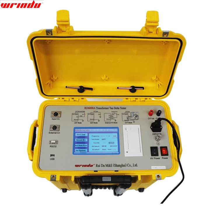
Distribution and power transformers are tested against the same principles but with different programmes, tolerances and levels of evidence, because their duty, size and consequences of failure differ. The distinction is not simply voltage: rating, impedance, cooling and the applicable standard all matter.
The practical question for a test engineer is which tests apply, which tolerances govern, and where the classification boundary sits for the standard or regulation that applies to your project.
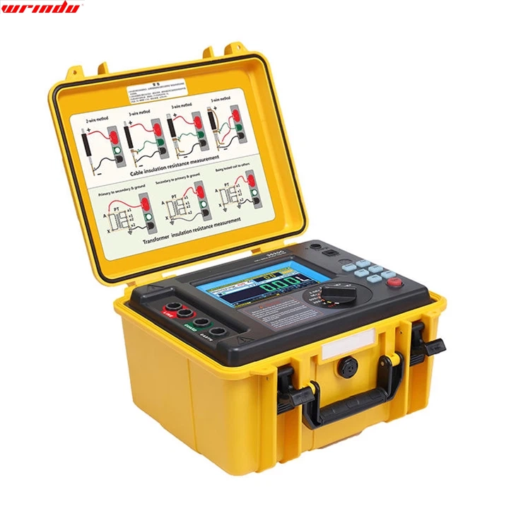
Use the table as a starting point for a project-specific test plan, then replace every entry with the requirement from the governing standard and contract. The table is a comparison aid, not a substitute for the specification.
A worked example makes the difference concrete. A utility purchasing a 2 MVA distribution transformer for a rural substation may specify routine tests only: ratio and vector group, winding resistance, insulation resistance and the dielectric checks defined by the standard for that class, with the manufacturer’s type test certificate accepted as design proof. The same utility purchasing a 100 MVA power transformer for a transmission substation will typically require the full routine set at every tap position, witness testing, and contractually agreed special tests such as short-circuit withstand or extended dielectric assessment, with the site programme repeated after transport. The measured quantities are similar, but the evidence depth is not, and the acceptance criteria for ratio deviation, losses and impedance are read from different clauses of the governing documents. Writing the plan this way, with the classification and the governing standard named for each unit, removes the ambiguity that appears when the words “power” and “distribution” are used loosely in a specification.
Witnessing and documentation belong in the comparison as well. On larger units, purchasers often witness the factory tests and sign the reports before dispatch, which makes the factory data part of the contract record rather than a document received after the fact. The same evidence logic applies on site: the commissioning team signs the site test record, and the comparison between the factory and site values is written into the handover documentation. When the classification boundary is disputed, the resolution comes from the governing standard and the contract terms, not from the equipment labels. That is why the test plan should state, for every unit, which standard edition applies, which classification the contract uses, and which tolerance clauses govern the measured quantities. A plan written that way survives changes of personnel, because the evidence and its basis are recorded together.
The same comparison logic also guides maintenance decisions later in life. A distribution transformer and a power transformer may sit on the same site, but their testing histories should be treated differently: the power unit’s more extensive baseline allows smaller changes to be detected with confidence, while the distribution unit may need a deliberate decision to add diagnostic depth when its condition or criticality changes. Revisit the classification when the duty changes, because a unit that starts life in distribution service can become critical to a growing network and justify a deeper programme.
Why Voltage Level Is Not the Only Boundary
It is common to call a transformer “distribution” if it feeds an end-user network and “power” if it operates in a transmission or large sub-transmission substation, but voltage alone is not a reliable boundary. Different standards and regulations draw the line differently: some classify by capacity ranges, some by whether the unit steps down toward end users, and some use a combination of voltage, rating and frequency. The same physical unit can even be classified differently under a utility specification and an efficiency regulation. For testing purposes, what matters is the standard or specification that governs the contract. Before comparing test items or tolerances, identify the governing document and its edition, and check how it classifies the unit in question. A classification statement without a cited standard is only an opinion.
How Standards Classify Power and Distribution Transformers
International practice is anchored in standard families such as IEC 60076 and the IEEE C57 series, each of which groups transformers for testing purposes. These documents define routine, type and special tests and, in some cases, apply different tolerances or different test requirements to units of different size and voltage class. The classification may not match the everyday use of the words “power” and “distribution”, which is exactly why the governing standard must be named in the test plan. Regional regulations can classify the same unit differently for efficiency purposes, using capacity bands and voltage limits that have nothing to do with the testing standard. Do not mix the two classification systems in one document. State clearly which classification applies to the test programme and which applies to any regulatory efficiency claim, and keep the references separate.Where the Test Programmes Differ
Both transformer families share the fundamental checks: turns ratio and vector group, winding resistance, insulation resistance and dielectric tests. The differences are in depth, number of measurements and additional tests. Larger power transformers typically justify more extensive measurement, including measurements at every tap position, more detailed dielectric assessment and, on critical units, additional diagnostic tests such as frequency response analysis and partial discharge measurement. Distribution transformers, produced in higher volumes, are more often tested with a compact routine programme that proves compliance efficiently. The difference is driven by economics and risk. The cost of an extensive programme is proportionally small on a large power transformer and proportionally large on a small distribution unit, while the consequence of an undetected defect scales in the opposite direction. That does not mean distribution transformers are tested carelessly; it means the programme is matched to the duty and the failure consequences.Routine, Type and Site Tests in Context
Routine tests are performed on every unit before dispatch, and the set is similar in kind across the family: ratio, resistance, insulation and dielectric checks. Type tests are performed on a representative unit of a design, and the selected set reflects the duty class, with larger units more likely to include lightning impulse and temperature-rise verification. Special tests are agreed between purchaser and manufacturer, and they are where the biggest programme differences appear: a purchaser may require short-circuit withstand testing on a large power transformer design, while a distribution transformer contract may add only a modest set of agreed extras. Site tests after transport and installation repeat the checks that verify nothing changed in transit: ratio, winding resistance, insulation and, where justified, frequency response or other diagnostic checks. The site programme for a power transformer is usually deeper than for a distribution unit, again reflecting the cost of an undetected transport defect. The sequence and depth belong in the site test plan, not improvised at the site.
How Acceptance Tolerances and Limits Are Set
Tolerances differ by transformer class and by the governing standard. For example, the acceptable deviation of the measured turns ratio from the nameplate ratio is defined by the applicable standard and can be tighter for larger power transformers than for small distribution units; the same logic applies to other quantities such as losses and impedance. These values are set by the standard or specification in force, not by a universal rule, and they must be read from the correct edition for the contract. Before quoting a tolerance in a report, verify three things: the standard or specification that governs the test, the clause that defines the limit, and the conditions under which the limit applies, including temperature and measurement method. A limit copied from an article or from a different transformer class is a common source of false acceptance and false rejection.Building a Comparison Table for Your Procurement
| Test area | Distribution transformers | Power transformers |
|---|---|---|
| Turns ratio and vector group | Routine check on every unit; usually at principal tap. | Routine check, typically at multiple tap positions with phase-by-phase comparison. |
| Winding resistance | Routine check; fewer taps and shorter settling expectations. | All taps where relevant, with temperature correction and baseline comparison. |
| Insulation and dielectric | Core programme defined by the standard for the class. | Deeper programme, potentially including partial discharge and impulse on type tests. |
| Diagnostics on site | Selected checks where the duty justifies them. | Broader set including frequency response analysis after transport or events. |
| Evidence depth | Compact but complete record per unit. | Extensive record supporting long-life asset decisions. |
Frequently Asked Questions
Is voltage the real difference between power and distribution transformers?
Voltage is a useful hint but not a reliable boundary. Standards and regulations classify transformers by different combinations of voltage, rating, frequency and application, and the same unit can be classified differently under different documents. Always name the governing standard before comparing test programmes.Which test items differ between the two families?
The shared fundamentals are the same, but depth and coverage differ: more tap positions, tighter tolerances, deeper dielectric assessment and more extensive site diagnostics are typical for power transformers, while distribution units are usually proven with a compact routine programme suited to high-volume production.Are acceptance tolerances different?
Yes, and the difference is defined by the applicable standard and transformer class, not by a universal rule. Verify the tolerance clause, its edition and its conditions before applying it to a measured result. For commissioning and site test instrumentation, see the transformer commissioning test equipment range, and for the lifecycle framework read What Tests Are Required for a Power Transformer.Related articles
 SF6 Leak Detector Sensitivity: Select a Method for the Inspection TaskKnowledge
 Cable Fault Locator Selection for Urban Networks: Routes, Noise and AccessKnowledge
 Substation Battery Load Bank Sizing: Duty, Voltage Range and Heat RejectionKnowledge
 CT Polarity, Ratio and Burden Testing: Find Wiring and Loading ErrorsKnowledge