
How to Interpret Transformer Turns Ratio Test Results
Send your test requirement — get a tailored solution and a quote within one working day.
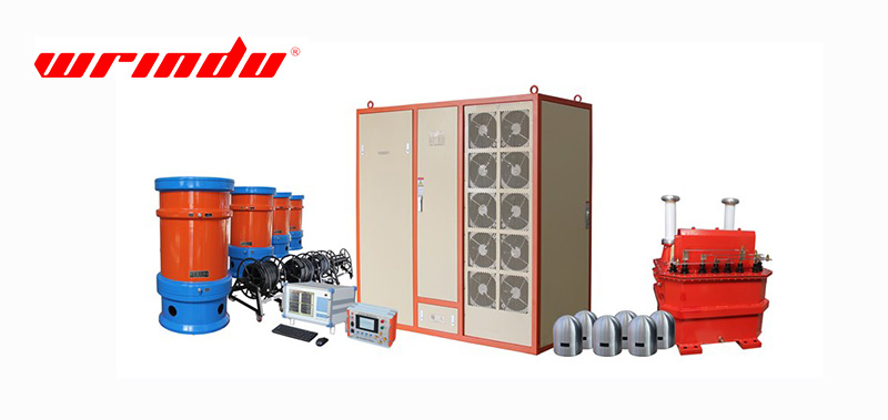
Interpret transformer turns ratio (TTR) test results by first verifying the nameplate, vector group and tap position, then comparing deviation, phase balance and repeatability against the reference applicable to that transformer. A single reading is not a verdict: interpret patterns across phases, taps and test dates, and escalate only what survives a corrected setup and a confirmatory retest.
Confirm the Nameplate and Vector-Group Inputs First
Every ratio result is only as good as the reference it is compared with. Before interpreting, confirm the nameplate ratio at the principal tap, the vector group symbol, the current tap position, and whether the test covers all phases or a selected winding pair. If the reference is entered incorrectly, a healthy transformer can appear to fail and a damaged one can appear normal.
Record the instrument settings used for the test, including excitation voltage and frequency. Different instruments and procedures can produce slightly different readings on the same transformer, so the interpretation must compare like-for-like data from the same instrument family and settings.
Identify the reference source explicitly in the record: the nameplate, the purchase contract, the applicable standard or the manufacturer’s documentation. Each source can define the ratio reference and the permitted deviation differently, and mixing sources across test dates is a common cause of false alarms. When a transformer has multiple windings, plan the test to cover each winding pair that the reference defines, and record which pair each reading belongs to.
Calculate and Record Ratio Deviation Consistently
Express the result as a deviation from the reference ratio, using one consistent formula and sign convention. The acceptable deviation is defined by the applicable standard, contract or manufacturer documentation for that transformer; do not apply a value from an unrelated source. Record the measured ratio, the reference ratio and the computed deviation for every phase and tap position tested.
Also record the electrical conditions: excitation voltage, frequency, test date and temperature. While the turns ratio itself is largely independent of temperature, the quality of the measurement and the comparison with previous tests depend on stable, documented conditions.
To keep the arithmetic consistent, fix the deviation formula in your procedure. For example, if the reference ratio is 100 and the measured ratio is 99.8, the deviation is expressed as a signed percentage of the reference; the same result must be signed and labelled identically in every report so that a later engineer does not have to guess the convention. Illustrative values like this are for showing the method only; always apply the tolerance defined for the actual transformer.
Compare Results Across Phases and Tap Positions
Compare phases with each other and each phase across its tap positions. A uniform offset across all phases and taps usually points to an input or reference problem. An isolated deviation on one phase may indicate a winding or connection issue on that phase, while a deviation that appears only at certain taps directs attention to the tap changer and its contacts.
Think of the tap profile as a curve: a healthy tap changer produces a smooth, monotonic ratio profile. A step or kink at one tap position is a stronger signal than the same deviation appearing uniformly, because it localises the evidence to the tap selector and transition contacts.
For delta-connected windings, remember that the measured ratio depends on the winding connection and the way the instrument references the phases. Confirm the vector group before judging phase balance, and compare phases only within the same winding pair and test configuration. A phase that looks different solely because the reference configuration changed is a setup issue, not a transformer finding.
Separate Test-Setup Errors from Transformer Conditions
Before attributing a deviation to the transformer, eliminate setup causes. Inspect test lead connections for corrosion, loose clips and incorrect terminal selection; confirm that shields and guards are connected as the instrument requires; and verify that the transformer is properly isolated, de-energised and grounded according to the test procedure.
Retest after cleaning and tightening any suspect connection. If the deviation disappears, record the corrected result as the valid one and note the setup issue. If it persists identically across repeated tests with controlled settings, the evidence begins to point toward the transformer or tap changer rather than the measurement.
- Lead clips on the correct bushings, with clean and tight contact surfaces.
- Shield and guard connections as required by the instrument manual.
- Transformer isolated, de-energised and grounded per the approved procedure.
- Tap position indicator matching the actual contact position.
- Instrument warm-up, supply voltage and calibration validity.
What Abnormal Patterns May Indicate
A persistent ratio deviation on one phase can be associated with inter-turn or winding issues, but ratio alone cannot confirm the mechanism. A deviation limited to one tap position suggests tap changer contact or selector problems. An impossible reading, far from any nameplate ratio, indicates a possible winding or connection change that requires immediate controlled investigation.
Do not convert these patterns into a diagnosis. Use them to decide which complementary tests to run and which records to assemble: winding resistance, excitation current, oil analysis and, where indicated, frequency response analysis. The ratio test identifies where the evidence is; the complementary tests help determine what it means.
Compare the current result with the transformer’s own history before judging severity. A small shift from an established baseline may be more meaningful than a larger deviation on a unit with no prior records, because the baseline removes unit-to-unit variation. If no baseline exists, treat the first test as the baseline and schedule the follow-up interval according to the maintenance procedure.
When to Add Winding Resistance or Excitation Testing
Add winding resistance testing when the anomaly could involve joints, contacts or winding conductors, because resistance is sensitive to the resistive path that ratio testing does not measure. Add excitation current testing when the anomaly could involve the core or parallel winding circuits, because magnetising current responds to changes in the magnetic circuit.
Sequence the tests to preserve evidence: correct the setup, confirm repeatability, then run the complementary measurement while the transformer is already isolated. Compare all results against the same baseline and document the reasoning that led to each additional test.
Excitation current testing is particularly useful when the ratio pattern suggests a parallel winding circuit or core-related change, because the magnetising current responds to the magnetic circuit rather than the resistive path. Winding resistance testing, in contrast, responds to the resistive path through joints, contacts and conductors. Running the two together separates electrical-path defects from magnetic-circuit changes more reliably than either test alone.
Documenting a Defensible TTR Test Result
The interpretation is only as defensible as its record. Record the transformer identification, nameplate data, vector group, tap position, instrument and calibration date, test settings, all phase readings, the reference used and the computed deviation, plus any retest and setup corrections. The table below shows an illustrative interpretation record; replace the reference bands with the tolerance applicable to your transformer.
| Tap | Phase A deviation | Phase B deviation | Phase C deviation | Pattern | Next step |
|---|---|---|---|---|---|
| 1 | Within reference band | Within reference band | Within reference band | Normal | Continue with tap 2 |
| 3 | Within reference band | Outside reference band | Within reference band | Phase-specific, tap-specific | Check tap changer contact; repeat; add winding resistance |
| 5 | Outside reference band | Outside reference band | Outside reference band | Uniform offset | Verify reference input and setup before further action |
Close the record with a factual conclusion: what was measured, what reference was used, which setup issues were corrected, and which follow-up is recommended. Keep the conclusion within the evidence.
Include the instrument serial number and calibration date in the record, and retain the raw readings in the export file rather than only the computed deviation. A defensible TTR record allows a second engineer to reproduce the comparison without re-running the test, which is the practical definition of audit-ready documentation.
Frequently Asked Questions
Does temperature affect turns ratio test results?
The turns ratio itself is essentially independent of temperature because it reflects the physical turn count. Temperature can influence connection quality and magnetisation behaviour, so record ambient and transformer conditions and keep comparison data consistent, but do not apply a temperature correction to the ratio itself unless your procedure specifies one.
Why does the vector group matter for interpretation?
The vector group defines how the three-phase windings are connected and how phase relationships are expressed. It determines which winding pairs are compared and how a deviation in one phase should be interpreted, so an incorrect vector group input can turn a healthy result into an apparent fault.
How do I confirm that a result is repeatable?
Repeat the measurement on the same tap position with the same leads, instrument and settings, without changing the setup. Results that agree within the instrument’s resolution confirm repeatability; results that drift or jump indicate a connection, interference or magnetisation problem that must be resolved before interpretation.
For the full set of tests a transformer requires at each lifecycle stage, refer to the complete power transformer testing checklist. If you need to qualify a turns ratio test system, compare power transformer testing equipment and request a technical proposal matched to your transformer record.
Related articles
 SF6 Leak Detector Sensitivity: Select a Method for the Inspection TaskKnowledge
 Cable Fault Locator Selection for Urban Networks: Routes, Noise and AccessKnowledge
 Substation Battery Load Bank Sizing: Duty, Voltage Range and Heat RejectionKnowledge
 CT Polarity, Ratio and Burden Testing: Find Wiring and Loading ErrorsKnowledge