
How to Interpret Transformer Insulation Resistance, PI and DAR Results
Send your test requirement — get a tailored solution and a quote within one working day.
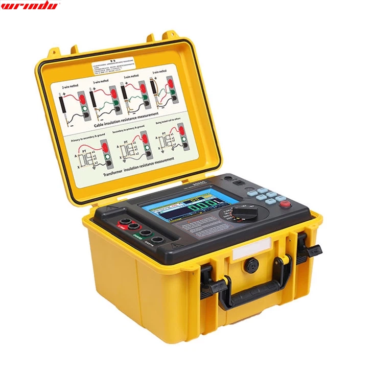
Insulation resistance (IR), polarization index (PI) and dielectric absorption ratio (DAR) are screening measurements that describe the condition of transformer insulation, but none of them produces a universal pass or fail number. The correct interpretation compares readings over time and across phases under the same conditions, applies temperature and moisture context, and treats reference ranges as guidance rather than verdicts.
A single IR value, quoted without conditions, cannot decide whether a transformer is safe to energize.
IR, PI and DAR: What Each Ratio Is Designed to Show
Insulation resistance is the resistance measured between a winding and ground, or between windings, when a DC voltage is applied. Because a good insulation system polarizes slowly under DC stress, the resistance rises over time as the charging and absorption currents decay. That time-dependent behaviour is the basis of the two ratios: PI is the ratio of the resistance measured at ten minutes to the resistance measured at one minute, and DAR is the ratio of the resistance at one minute to the resistance at thirty or sixty seconds, depending on the convention used. Each ratio answers a different question. DAR gives a faster indication of the same polarization behaviour and is useful when time is short. PI is the more established screening index for transformer insulation and is often recorded where a longer measurement is practical. Both compare the shape of the resistance rise, which is why they are less sensitive to the absolute level than a single IR reading and why they are quoted together with IR rather than instead of it.
Test Voltage, Duration and Temperature Correction
The test voltage must be selected for the winding insulation and the applicable guidance; using a voltage that is too high can stress aged insulation, while a voltage that is too low may not produce a stable reading. The correct choice depends on the rated voltage of the winding, the insulation system and the guidance that governs the test, so it cannot be reduced to a single number for every transformer. Record the voltage used with every result. Temperature has the strongest influence on insulation resistance. Resistance falls as temperature rises, and the change can be large enough to hide a real deterioration or to create a false alarm. Compare readings taken at similar winding temperatures, or correct them to a common reference temperature using a method appropriate to the insulation system. Without temperature context, comparing this year’s summer reading with last year’s winter reading is not a valid trend.Reference Ranges Are Not Universal Verdicts
Published guidance gives reference ranges for IR, PI and DAR, and the ranges differ between sources, between equipment types and between editions of the same document. A value described as “good” for one insulation system may be marginal for another, and a transformer manufacturer may set different thresholds from a maintenance standard. The reference ranges are screening aids that help you decide which readings deserve attention; they are not acceptance criteria unless the governing specification says so. This is why the interpretation rule is consistent: state the source and conditions of every reference range you use, apply the same range across time and phases, and never convert a screening range into a pass or fail verdict without the authority of the applicable specification. When a range and a verdict are both needed, the verdict comes from the document that governs the decision, not from the closest article. The table below separates reference ranges from verdicts. Ranges help screen; the verdict must come from the document that governs the decision.| Indicator | Typical guidance reference range (context-dependent) | What the reading indicates | Verdict source |
|---|---|---|---|
| IR at one minute | Varies by guidance, voltage class and conditions; compare with the unit’s own baseline | A snapshot of insulation condition at that voltage and temperature | Governing specification or OEM guidance, never a range table alone |
| DAR | Fast polarization indicator; ranges vary by guidance and convention | Absorption behaviour of the insulation | Governing specification or OEM guidance |
| PI | Polarization behaviour over ten minutes; ranges vary by equipment and guidance | Screening signal for moisture or deterioration trends | Governing specification or OEM guidance |
| Trend across tests | Change against baseline at the same conditions and tap position | Developing condition or seasonal variation | Engineer review with the full history |
Reading Trends Across Time and Phases
The most defensible interpretation compares three directions: the unit against its own history, the phases against each other, and the winding-to-ground readings against winding-to-winding readings. A winding whose IR has fallen steadily over several tests, or one phase that is clearly lower than the other two under the same conditions, is more significant than a single low number. A uniform low reading across all windings may point to a common cause such as high moisture or a shared condition, while a single low phase points toward that winding’s insulation path. Trend comparison requires identical test conditions. Record the tap position, test voltage, duration, temperature and connections every time, and compare like with like. A trend built from differently configured measurements is not a trend; it is a sequence of unrelated snapshots.
Common Errors That Make the Numbers Meaningless
The largest errors come from the test itself. Testing without proper isolation means the reading includes parallel paths and is not a winding measurement. Connecting without guarding allows surface leakage to dominate, especially on damp bushings. Reading at the wrong time, comparing readings at different durations, or testing at different voltages all destroy comparability. Residual charge from a previous test, or residual magnetism in the core from DC resistance testing, can also distort the first reading. Discharge discipline is part of the measurement. After a DC insulation test, the winding holds charge and must be discharged and verified before connections are changed; the same discharge step belongs in the record. If a reading looks wrong, repeat it after the conditions are corrected instead of accepting a number that cannot be explained.When to Escalate Beyond IR/PI/DAR
IR, PI and DAR cannot identify the cause of a deterioration. When the trend or the phase comparison signals a change, the next step is to add tests that separate the possible causes: tan delta measurement for dielectric loss and moisture indicators, excitation or turns-ratio checks for winding-related effects, and, where mechanical change is suspected, frequency response analysis. The tan delta interpretation is covered separately in the tan delta results guide in this series, and the wider test programme is described in What Tests Are Required for a Power Transformer. Escalation is a decision to gather more evidence, not a prediction of failure. Record the finding, the conditions, the trend and the recommended next test, and hand the decision to the engineer responsible for the unit. Screening tests keep their value when they are allowed to do what they do best: raise the right questions at the right time. A worked example shows how the pieces fit together. A 33 kV winding measured 850 MΩ at one minute and 1,700 MΩ at ten minutes on its previous test, giving a PI of 2.0 at 20 °C winding temperature. This year the same winding, tested at 26 °C with the same instrument and voltage, reads 520 MΩ at one minute and 780 MΩ at ten minutes, a PI of 1.5. The absolute values have fallen, but temperature explains part of the change, so the comparison should be made after temperature correction or at a comparable season. The PI drop from 2.0 to 1.5 is the more significant signal because it is less affected by the absolute level, and it justifies adding a tan delta measurement and reviewing the moisture and oil records before the next maintenance decision. Reporting the raw values, the temperatures and the ratio trend in this order gives the responsible engineer the evidence needed to decide whether the change is seasonal variation or the start of a deterioration trend. When time is limited, DAR can serve as the first screening step and PI can be reserved for the windings that matter most or the readings that look marginal. The two ratios use the same underlying physics, so a fast DAR screen that is clearly healthy can reduce the need for a ten-minute measurement on every winding, while a marginal DAR reading justifies the longer PI measurement on that winding. Whatever screening order is used, record it in the test procedure so that the same logic applies at every site and every season.Frequently Asked Questions
What is DAR and how is it different from PI?
DAR is the dielectric absorption ratio, usually the insulation resistance at one minute divided by the resistance at thirty or sixty seconds, while PI is the polarization index, the resistance at ten minutes divided by the resistance at one minute. Both measure the same polarization behaviour; DAR is faster, and PI is the more established screening index for transformer insulation.When is DAR waived in favour of PI?
Some guidance waives the DAR or PI calculation when the one-minute insulation resistance is very high, because the absorption behaviour is already consistent with healthy insulation. The specific condition depends on the governing guidance, so verify the threshold and its basis before relying on it.Can I compare IR readings taken at different temperatures?
Only after correcting them to a common reference temperature using a method appropriate to the insulation system. Raw IR changes strongly with temperature, so comparing uncorrected readings from different seasons is not a valid trend. Record temperature with every measurement. For the instruments used in these measurements, see the transformer maintenance test equipment range.Related articles
 SF6 Leak Detector Sensitivity: Select a Method for the Inspection TaskKnowledge
 Cable Fault Locator Selection for Urban Networks: Routes, Noise and AccessKnowledge
 Substation Battery Load Bank Sizing: Duty, Voltage Range and Heat RejectionKnowledge
 CT Polarity, Ratio and Burden Testing: Find Wiring and Loading ErrorsKnowledge