Electrical resistance testing
As a Grounding and Insulation Resistance Tester Manufacturer, Wrindu has established a mature team covering all aspects of R&D, production, sales, and service after more than ten years of development. We specialize in producing customized high-voltage insulation resistance testers that feature comprehensive insulation resistance parameter testing functions and excellent anti-interference capabilities.Currently, we have provided high-quality testing equipment to the power industry in over 50 countries, including the Ethiopian Electric Power Company, Uganda Electric Power Company, and Dubai Electricity Company. In addition to our own brand products, we also offer professional OEM and ODM customized services tailored to our customers’ specific needs.For more product information or any special requirements, please feel free to contact us. We are committed to providing you with professional pre-sales and after-sales services.


What Is Grounding And Insulation Resistance Tester ?
An grounding and insulation resistance tester,also known as a megger or megohmmeter, is a vital tool for electricians to assess the effectiveness of electrical insulation.These devices play a critical role in the electrical sector for ensuring the reliability of insulation in power lines, electrical cables, and various types of electrical machinery. The primary goal is to detect any issues with the insulation, such as damage or wear, that could lead to electrical failures. Electricians rely on these tests to uncover hidden dangers and to maintain the performance of equipment like electric motors, power transformers, and conduit systems. Essentially, a higher measurement of insulation resistance suggests that the insulation is more robust and less prone to causing electrical accidents.
What are advantages of Grounding And Insulation Resistance Tester ?
01/ High anti-interference technology
Stable test capability in scenarios with large distributed capacitance and in environments with strong electromagnetic interference (e.g., substations)
02/ Multiple measurement modes
PI, DAR calculation formula can be self-selected, self-setting test voltage, self-setting test duration, can provide users with a variety of options to facilitate the needs of special scenarios.
03/ Automatic discharge function
Automatically and quickly releases the charge of the DUT after the test, without the need for an external discharge circuit.
04/ High-capacity storage
Large-capacity test record memory, can automatically store a total of 1000 groups of real-time test data with the test date, test timing.
Types of Grounding And Insulation Resistance Tester
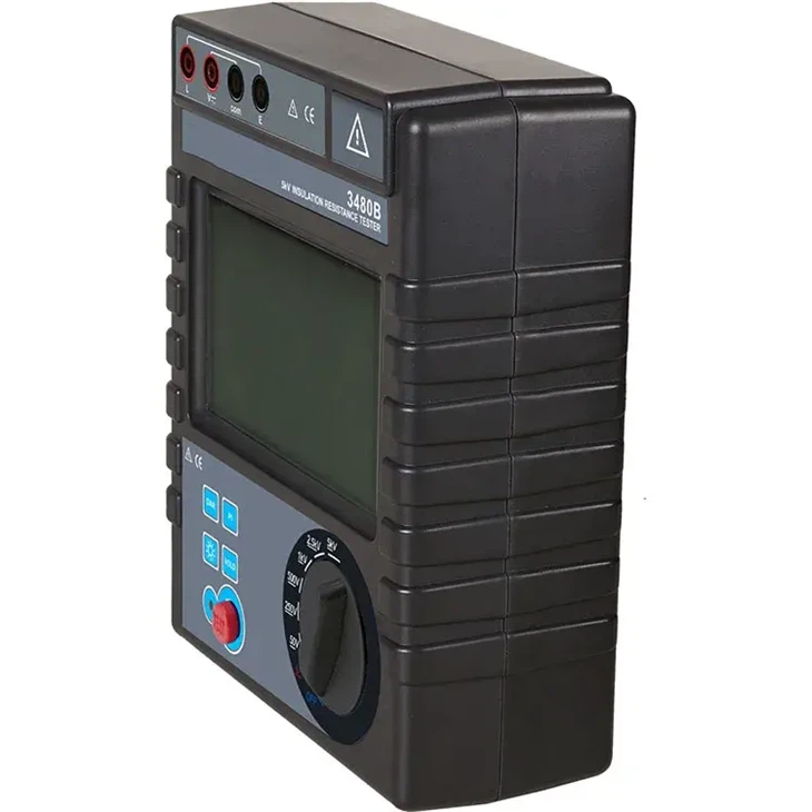
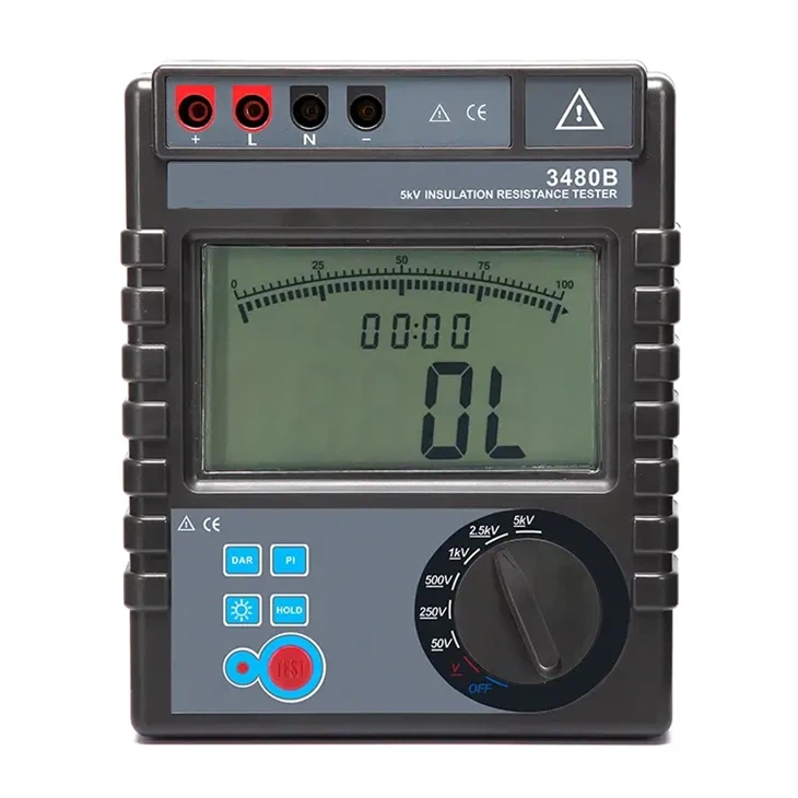
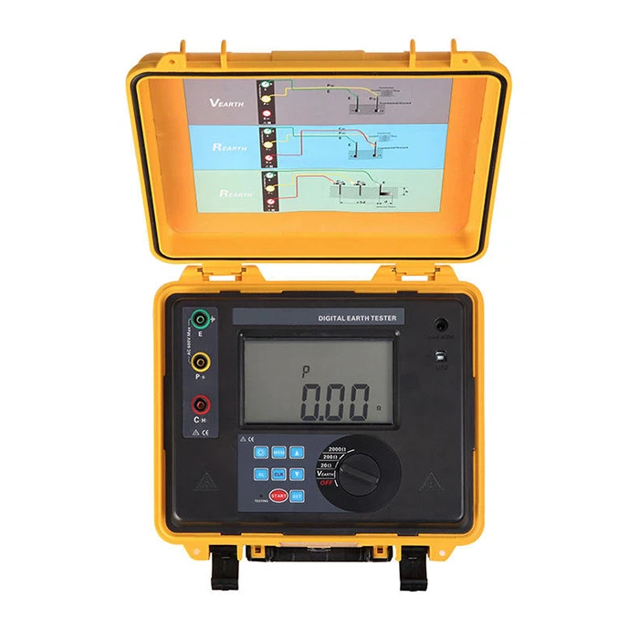
Insulation resistance meter
Insulation Resistance Meter is also known as Digital Megohmmeter, Insulation Resistance Tester, etc. It is used for insulation resistance testing. Megohmmeters can quickly and easily determine the condition of the insulation of wires, generators and motor windings. Having a smaller size and weight, insulation resistance meters are easy to carry around, while the testing capabilities can be relatively limited.

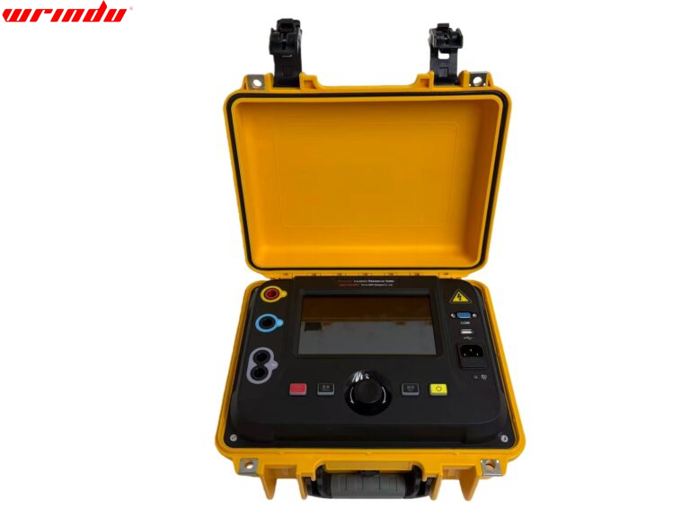
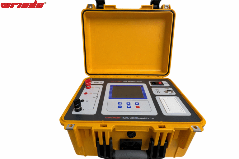
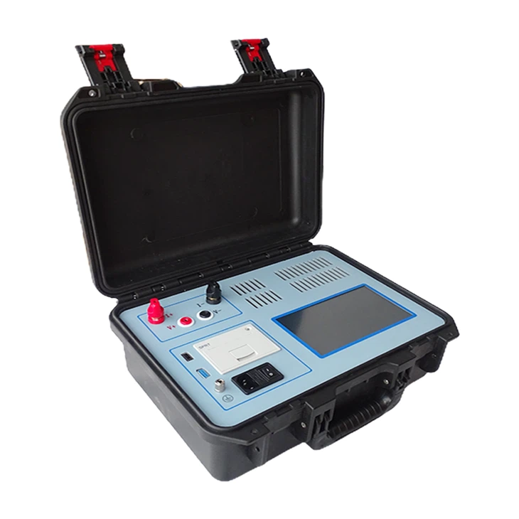
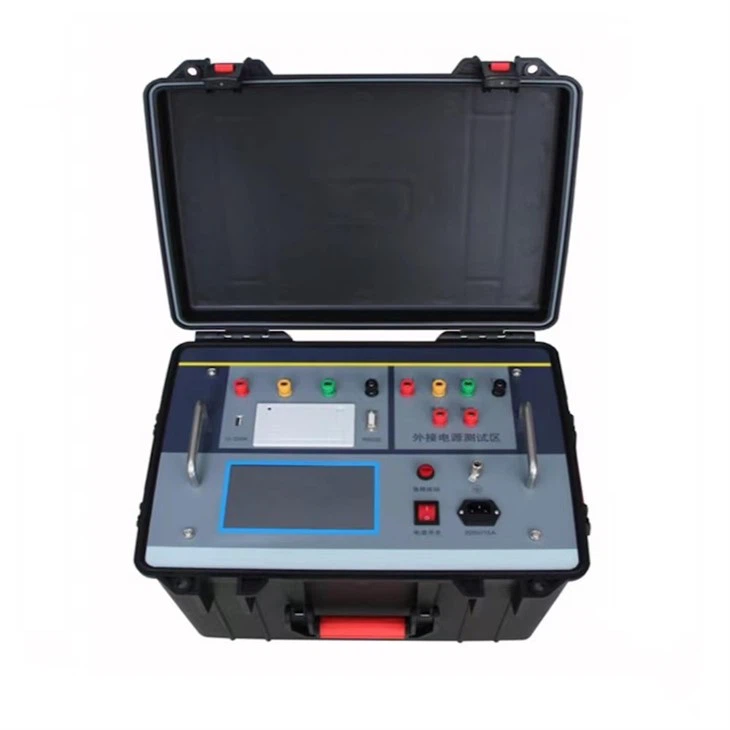
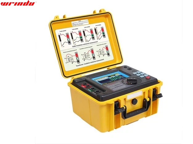
High voltage insulation resistance tester
Insulation resistance tester, the instrument has a perfect variety of insulation resistance parameter test function and good anti-interference ability, can be used for cable, motor, generator, transformer, transformer, high-voltage switch, lightning arrester and other equipment insulation resistance test. The volume and weight of the equipment is larger than megohmmeter, but the function is more perfect, the test range is wide.
Application of Grounding And Insulation Resistance Tester
Maintenance of electrical equipment
In the maintenance of electrical equipment, an insulation resistance tester can be used to test the insulation of the equipment to find possible faults or defects, as well as to prevent accidents caused by insulation failure of the equipment.
Electrical equipment testing
In the manufacturing process of electrical equipment, an insulation resistance tester can be used to test the insulation performance of the product to ensure the safety and reliability of the product.
Building electrical safety testing
In building electrical safety testing, an insulation resistance tester can be used to test the insulation of electrical equipment in the building to ensure the safety performance of building electrical.
Power industry testing
In the power industry, insulation resistance testers can be used to test the insulation of transmission lines, substations, power equipment, etc. to ensure the safety performance of the power system.
Application of Grounding And Insulation Resistance Tester
Environmental conditions: Do not work alone or in explosive gas, steam or high dust environment.
Voltage check: Before testing, make sure that the tester voltage display is not higher than 36V.
Power off of the product under test: Confirm that the tested device is in a power-off state. This instrument is not allowed to be used to test live device.
Voltage range determination: Confirm that the withstand voltage of the tested device is within the output voltage range of theselected test gear.
Electric charge release: After the test, do not take away the test line when the voltage is higher than 36V to ensure that the distributed capacitor electric charge is completely discharged.
Components of Grounding And Insulation Resistance Tester
Outside case
Outside case
Outside case
Outside case
Outside case
Outside case
Compared with traditional Grounding And Insulation Resistance Tester , our this product
Complete insulation test function
Perfect measurement feature: insulation resistance (IR), polarization index (PI), dielectric absorption ratio (DAR), step voltage (STEP), ramp (RAMP), dielectric discharge index (DD), distributed capacitance measurement (CAP), voltage measurement (V)
Custom measurement modes
Custom setting measurement mode: PI, DAR, and DD calculation formulas can be selected to provide users with multiple choices. Custom setting voltage mode: the test voltage and test duration can be set freely, which is convenient for special sites.
Automatic monitoring function
Voltage monitor: Automatically monitor the live voltage of the measured object. The voltage exceeding 36V will automatically prohibit the test from effectively protecting the instrument and theoperator. Current monitor: Automatic display of the current of the test circuit.Temperature monitor: Automic displays the temperature and humidity of the tester inside.
Automatic discharge function
Automatic discharge function, automatically and quickly releases the electric charge of the tested object after the test, with no need for an external discharge circuit.
FAQ
Q: Should an insulation resistance test be 250V or 500V?
A: For insulation resistance tests, use 500V when testing between SELV/PELV and other live circuits, but opt for 250V when testing within SELV and PELV conductors or between PELV conductors and protective conductors.
Q: What is the acceptable IR result?
A: An acceptable insulation resistance (IR) reading is crucial. Generally, it should meet a minimum standard of 1 megohm for every 1000 volts of the system’s operating voltage to be deemed suitable for most purposes.
Q: How do I choose an insulation tester?
A: When selecting an insulation tester, it’s essential to pick one that can provide the required test voltage. Insulation testers vary in their capabilities; some offer a maximum of 1,000 V DC, whereas others can deliver up to 5,000 V DC or higher for testing purposes.
Q: What is the maximum insulation resistance?
A: The maximum insulation resistance is typically guided by a standard: it should ideally be around one megohm per 1,000 volts of the equipment’s operating voltage, and it should not fall below one megohm as the baseline minimum.
Q: How to calculate insulation resistance?
A: To determine insulation resistance, you can use a straightforward method based on Ohm’s law. By applying a known voltage to the insulation and measuring the resulting current, you can use the formula R = U/I to figure out the resistance. Here, U represents the voltage applied, I is the current that flows, and R is the insulation resistance you’re calculating.
Q: Why do we do insulation resistance at 500V?
A: The standard practice of conducting insulation resistance tests at 500V is due to the fact that it’s one of the typical test voltages. Utilizing a higher voltage like this helps to apply a more significant stress on the insulation, which can lead to more precise and reliable outcomes.
Q: What is normal IR range?
A: In the realm of IR spectroscopy, covalent bonds characteristically exhibit absorption within a spectrum of 600 to 4000 cm-1. The spectral plot generally highlights the specific wavelengths at which different types of bonds are absorbed. Take, for example, a pronounced absorption band in the region of 2200-2400 cm-1, which could be indicative of a C-N or a C-C triple bond being present.
Q: What is the acceptable IR value?
A: Yes, insulation resistance can be tested at 250V DC. After all wiring has been initially tested at 500V, an extra test at 250V can be performed once the electronic equipment is connected and before it’s powered up. For this test, the insulation resistance should meet or exceed a minimum of 1 megohm.
Q: What is the IEC standard for insulation resistance test?
A: The International Electrotechnical Commission (IEC) sets the standard for insulation resistance testing in IEC 60270. This standard outlines the recommended practices and methods for conducting insulation resistance measurements on a wide range of electrical systems and apparatus. It is a globally accepted benchmark in the electrical engineering profession.
Q: What is ideal insulation resistance?
A: The ideal insulation resistance is generally defined as being about one megohm for every 1,000 volts of the equipment’s operating voltage, setting a baseline minimum of one megohm. To illustrate, a motor designed for 2,400 volts should ideally exhibit an insulation resistance of no less than 2.4 megohms.
Q: Can you test insulation resistance at 250V?
A: An acceptable insulation resistance (IR) value generally falls within a range of 100 megohms to 100 gigohms. For electric motors, the minimum acceptable IR should be at least one megohm per kilovolt of the motor’s rating plus one, though this can vary based on the specific motor requirements. There are also specific guidelines for other equipment like tap changers and cables. Upholding the right IR values is crucial for preserving the condition of the insulation.
Q: What happens if insulation resistance is high?
A: An acceptable insulation resistance (IR) value generally falls within a range of 100 megohms to 100 gigohms. For electric motors, the minimum acceptable IR should be at least one megohm per kilovolt of the motor’s rating plus one, though this can vary based on the specific motor requirements. There are also specific guidelines for other equipment like tap changers and cables. Upholding the right IR values is crucial for preserving the condition of the insulation.
Q: How do I select test voltage for an insulation test?
A: To select the test voltage for an insulation test, it’s advisable to start with a lower voltage if you’re uncertain. A general guideline is to use a test voltage that’s about twice the normal operating voltage of the equipment. So, for instance, equipment rated for 460 V to 600 V is commonly tested at 1000 V. Ensure that the test leads remain connected after the test is stopped to allow the insulation tester to discharge any remaining test voltage safely.
Q: What is a bad insulation resistance reading?
A: A bad insulation resistance reading is typically indicated by a Polarization Index (PI) value below 1.0, which suggests that the insulation’s resistance has decreased over time since the test began. Readings between 1.0 and 2.0 suggest questionable insulation quality, while values from 2.0 to 4.0 are considered good. Insulation resistance readings above 4.0 are regarded as excellent.
Q: What are the two methods of insulation resistance testing?
A: Insulation resistance testing primarily involves two key methods: the spot reading test and the time resistance test. Additionally, the step voltage test is also a recognized technique, although it’s less common than the first two.
Q: What is the principle of insulation resistance tester?
A: The principle behind an insulation resistance tester is based on Ohm’s law. The tester works by applying a known voltage (V) across the insulation of the target being measured. It then measures the current (I) that flows through the insulation due to the applied voltage. Using the formula Rx = V/I, the insulation resistance (Rx) is calculated by dividing the applied voltage by the measured current. This method provides an assessment of the insulation’s ability to resist the flow of electrical current.