Our tenet is to improve and perfect our products constantly, so there may be a little difference between the instrument you purchased and the user manual. If there is any change, we will not be able to inform you in time, please understand! If you have any questions about our products, please contact us; we will serve you wholeheartedly!
If you are interested in this tester, you are welcome to click on the yellow font to contact us.
Through this article, you will learn:
- 1. Introduction
- 2. Performance and Feature
- 3. Product Technical Parameters
- 4. Tester Structure
- 5. Safety Tips
- 6. Measurement Method
- 7. Consult Test Record
- 8. Normal Wiring Connection Method
- 9. Battery and Charge
- 10. Instrument Maintenance
Safety Warning
Please read the following safety precautions carefully to avoid personal injury and prevent damage to this product or any other products connected to it. At the same time, to avoid possible dangers, this product can only be used within the specified range.
- Before the test, please ensure the tested object is in an off state, or the power has been disconnected. These insulation testers cannot be used for testing live equipment and devices.
- Before the test, please make sure that the withstand voltage of the tested object is above the output voltage gear, and do not use the insulation resistance tester as a withstand voltage tester.
- Before the test, please ensure that the instrument and accessories are in good condition and that the instrument shell and the insulation layer of the test wire are not damaged, exposed, or broken.
- Before testing, ensure the tester voltage display is not higher than 36V.
- The instrument outputs high voltage; please be sure to connect the test line first and confirm that the connecting plug of the test line has been tightly inserted into the instrument interface port. Press the test button after the hand leaves the test line. Otherwise, there is a risk of electric shock.
- During the test, do not switch gears; touching the exposed conductor and measuring circuit is strictly forbidden.
- After the test, do not discharge in an external short circuit; the tester has the function of automatic rapid discharge. After finishing the automatic discharge, the screen shows the output voltage lower than 36V, then remove the test line to ensure that the equipment and components are fully discharged.
- When removing the test line after the test, please hold the finger protector back end of the test line clip.
- Do not use the instrument when the hands and surface are wet. Usinge the tester in an environment of explosive gas, steam, or dust is forbidden.
- Do not place and store the meter in high temperature&humidity or dewy places and under direct sunlight for a long time.
- Use, disassembly, calibration, and repair of this tester must be performed by authorized personnel.
- The detector’s use, disassembly, and maintenance shall be handled by authorized personnel.
- The instrument manual with the danger mark “
“, users must follow instructions to operate safely.
1. Introduction
- RD3210E digital insulation resistance tester is a high-performance high voltage insulation resistance tester of sound research and development by our company. The instrument has the perfect testing function of various insulation resistance parameters and excellent anti-interference ability, which can be used to test the insulation resistance of large capacity high voltage electrical equipment and transmission lines in substations withintenseg induction electric environments. The insulation testers adopt an actual color touch screen, and all the test data and battery power are displayed on the same screen for viewing clearly. The combination of a knob switch and a button makes the operation very simple. The user does not need to memorize the operation method but click “HELP” on the screen to pop up the operation method, effectively guiding the user to operate the instrument. The instrument has the function of rapid discharge; the charge of the tested object is released automatically after the test. The instrument’s voltage monitor automatically monitors the measured object’s live voltage; when the voltage exceeds 36V will automatically prohibit testing and effectively protect the instrument and operator.
- The insulation testers adopt a large-capacity rechargeable lithium battery pack. The test timer of the instrument automatically records the test time and stores the test results with date and time. The touch screen can quickly check the historical data recorded. The fully isolated USB interface can safely upload the test data to the Py. The instrument is equipped with the test line with double insulation and shielding layer, and the high voltage rod is fitted with a replaceable crocodile clip and hook, which can adapt to various test places. The insulation testers adopt a strong double-shell structure, and the outer case of the instrument has a protection rating of IP65, which can prevent the intrusion of moisture and dust as well as prevent impact in the transportation and storage process, effectively protecting the instrument.
2. Performance and Feature
- 1. A 5-inch touch colourful screen displays the test data on the same screen. It is very convenient to do the test operation and view history data.
- 2. Output rated voltage :
RD3205E: 50V, 250V, 500V, 1kV, 2.5kV, 5kV
RD3210E: 50V, 250V, 500V, 1kV, 2.5kV, 5kV, 10kV
RD3215E: 50V, 250V, 500V, 1kV, 2.5kV, 5kV, 10kV, 15kV.
- 3. Insulation resistance range: 0.005MΩ ~ 10TΩ (RD3205E), 0.005MΩ~ 20TΩ (RD3210E), 0.005MΩ~ 30TΩ (RD3215E).
- 4. Max short circuit current 7mA.
- 5. Large output power, strong anti-interference ability, and stable test capability in large distributed capacitance sites (long cables) and intense electromagnetic interference environments (substations).
- 6. Perfect measurement feature: insulation resistance (IR), polarization index (PI), dielectric absorption ratio (DAR), step voltage (STEP), ramp (RAMP), dielectric discharge index (DD), distributed capacitance measurement (CAP), voltage measurement (V)
- 7. Custom setting measurement mode: PI, DAR, and DD calculation formulas can be selected to give users multiple choices.
- 8. Custom setting voltage mode: the test voltage and duration can be set freely, which is convenient for unique sites.
- 9. Voltage monitor: Automatically monitor the live voltage of the measured object. If the voltage exceeds 36V will automatically prohibit the test from effectively protecting the instrument and the operator.
- 10. Current monitor: Automatic display of the current of the test circuit
- 11. Temperature monitor: Automic displays the temperature and humidity of the tester inside.
- 12. Automatic discharge function automatically and quickly releases the electric charge of the tested object after the test, with no need for an external discharge circuit.
- 13. Large capacity rechargeable lithium battery pack 14.8V 6200mAh, to ensure long-term testing work.
- 14. Large-capacity test record memory: test records can be browsed and analyzed directly by the tester and automatically store the real-time test data with the test date and timing.
- 15. USB communication and upload function: the record data can be uploaded to the computer store and analyzed.
- 16. Bluetooth communication function, which can upload the testest result to mobile.
- 17. Double shell structure, which is durable and the protection level reaches IP65.
3. Product Technical Parameters
(1) Insulation resistance range and accuracy
Rated Voltage | Insulation Resistance Rage | Accuracy | Remark |
50V | 0.005MΩ ~ 10.0GΩ | ±5%rdg±3dgt | |
10.0GΩ ~ 100GΩ | ±10%rdg±3dgt | ||
250V | 0.05MΩ ~ 50.0GΩ | ±5%rdg±3dgt | |
50.0GΩ ~ 500GΩ | ±10%rdg±3dgt | ||
500V | 0.1MΩ ~ 100GΩ | ±5%rdg±3dgt | |
100GΩ ~ 1.00TΩ | ±10%rdg±3dgt | ||
1kV | 0.5MΩ ~ 200GΩ | ±5%rdg±3dgt | |
200GΩ ~ 2.00TΩ | ±10%rdg±3dgt | ||
2.5kV | 1MΩ ~ 1TΩ | ±5%rdg±3dgt | |
1TΩ ~ 5.00TΩ | ±10%rdg±3dgt | ||
5kV | 2MΩ ~ 2.00TΩ | ±5%rdg±3dgt | |
2.00TΩ ~ 10.0TΩ | ±10%rdg±3dgt | ||
10kV | 5MΩ ~ 4.00TΩ | ±5%rdg±3dgt | |
4.00TΩ ~ 20.0TΩ | ±10%rdg±3dgt | ||
15kV | 10MΩ ~ 6.00TΩ | ±5%rdg±3dgt | |
6.00TΩ ~ 30.0TΩ | ±10%rdg±3dgt |
1 TΩ (Tera ohm) =1000 GΩ = 1012Ω
1 GΩ (Giga ohm) =1000 MΩ = 109Ω
1 MΩ (Mega ohm) =1000 kΩ = 106Ω
(2) Technical specification
Function | insulation resistance (IR), polarization index (PI), dielectric absorption ratio (DAR), step voltage (STEP), ramp (RAMP), dielectric discharge index (DD), distributed capacitance measurement (CAP), voltage measurement (V) |
Power Supply | Rechargeable lithium battery pack 6.2Ah/14.8V |
Rated Voltage | RD3205E: 50V, 250V, 500V, 1kV, 2.5kV, 5kV RD3210E: 50V, 250V, 500V, 1kV, 2.5kV, 5kV, 10kV RD3215E: 50V, 250V, 500V, 1kV, 2.5kV, 5kV, 10kV, 15kV |
Output Voltage Accuracy | (5% ~ 10%) ±10V |
Insulation Resistance Range | RD3205E:0..005MΩ~10.0TΩ RD3210E:0.005MΩ~20.0TΩ RD3215E:0.005MΩ~30.0TΩ |
Short Circuit Current | 7mA |
Capacitance Measurement | Range: 10nF ~ 200μF; Accuracy: ±10%rdg ± 10nF |
Voltage Measurement | Range: DC:0V~1000V; Accuracy: ±5%rdg±3V Range: AC: 0V~700V; Accuracy: ±5%rdg±3V |
Custom Setting Output Voltage | RD3205E: 40~5kV, RD3210E:40V~10kV, RD3215E: 40V~15kV |
Custom Setting Test Time | 10s ~ 3600s |
Real-Time Current Value | Display test current value, current display range: 0.001nA ~ 7.5mA |
Real-Time Voltage Value | Automatically monitoring the voltage of the measured object. When the voltage exceeds 36V, and will automatically prohibit to test to protect the instrument and the operation. |
Test Timer | Automatically record test duration, timing range: 0s ~ 9999s |
Test Time | After selecting the DAR, PI, and DD test options, the test will be stopped immediately after the test result is obtained; in the custom test mode, the test duration can be set by the user; in the standard test mode, the test time is not limited, and the operator can manually stop the test. |
Store Function | Automatically store the test date, time, and timing, a total of 1000 groups, which can view and replay the stored test record |
USB Communication | Yes, upload the test record to the PC through the USB cable |
Bluetooth Communication | Yes, it can connect to the Android mobile or others with the Bluetooth communication device. |
Battery Power Indication | With the battery power indication, when the battery voltage is low will be reminded to charge in time.e |
Automatic Shutdown | After 15 minutes, es start-up will shut down automatically without any operation.ion |
Tester Dimension | 280mm×260mm×160mm |
Tester Weight | Host: 4326g (including the battery); Total weight: 6.96kg (Accessories) |
Protection Level | Close the case IP65; open the case IP40 |
Working Environment | -20℃ ~ 50℃; 80%RH |
Store Environment | -25℃~65℃; 80%RH |
Insulation Resistance | 50MΩ (1000V, between the test circuit and shell) |
Withstand Voltage | AC 3kV 50Hz 1min (between the test circuit and shell) |
Suitable Safety Standard | IEC61010-1, IEC61326-1 |
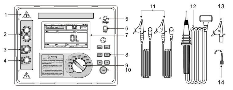
4. Tester Structure
1 | Outside case |
2 | LINE: high voltage terminal (red) |
3 | GUARD: protection terminal (green) |
4 | EARTH: grounding terminal (black) |
5 | Charge interface |
6 | USB interface |
7 | Tocolourfulrful screen |
8 | Function selection button |
9 | Measurement range selection switch |
10 | Test button |
11 | Test line with alligator clip (each 1pc of green and black) |
12 | HV test line(red) |
13 | HV test line accessory – alligator clip |
14 | HV test line accessory – test hook |
5. Safety Tips
To avoid electric shock or personal injury, follow these guidelines:
1. Do not work alone or in explosive gas, steam, or high dust environments.
2. Before testensure that the tester voltage display is not above 36V.
3. Confirm that the tested device is in a power-off state. This insulation tester is not allowed to be used to test live devices.
4. Confirm that the withstand voltage of the tested device is within the output voltage range of the selected test gear.
5. After the test, do not remove the test line when the voltage exceeds 36V to ensure that the distributed capacitor electric charge is completely discharged.
6. Check whether the insulation of the test line is damaged, if damaged, please replace the cable.
7. Insert the test line into the correct port othe,; raisinghigh voltage may be output to dangerous parts.
8. Do not touch the test line clip and the connected part of the tested deviceDuringng the test, If touched may cause an electric shock accident.
9. When removing the test line after the test, please hold the finger protector back end of the test line clip.
6. Measurement Method
(1) Measurement steps
1) Non-destructive inspection of the instrument, confirm the tester and test line are not damaged.
2) Check the battery voltage, ch and indicator after starting the tester; if the power is too low, please charge first.
3) Check the storage space for test records, and check the used rate of the storage space in the lower right corner after starting up the tester. If the remaining space is small should be cleared in time.
4) Correct the wiring connection, insert the test cable into the corresponding jack, and connect the tested device.
5) Check whether the test device is live, and it is strictly forbidden to test when it is live.
6) Confirm the test voltage gear to prevent the tested device from being damaged under the selected voltage gear.
7) Set the measurement mode can choose the calculation formula when measuring DAR, PI, and DD parameters.
8) Test and record the measurement results.
9) After the test, the insulation tester should be cleaned of dirt and proper storage in a ventilated and dry place.
(2) Rotary switch & button function
Rotary Switch Diagram
Button Diagram
1) Normal test, press the TEST button directly to start the test after selecting the voltage gear and press the TEST button again to stop the test.
2) If you need your needest modes or test items, you should press the corresponding button before the test and then press the TEST button to start the test; it is not allowed to change the test mode or option during the test.
3) RAMP and STEP modes can only be selected in preset gear, and these codes cannot be chosen in V and VS gear.
4) When selecting the dielectric discharge DD mode, the capacitance CAP will be chosen automatically because the distributed capacitance of the tested device needs to be measured when calculating DD.
5) When selecting the dielectric absorption ratio(DAR), polarization index(PI), and dielectric discharge(DD), there will be a test duration requirement, and the test will be automatically stopped after the corresponding test result is collected; if the test is stopped by pressing the test button in advance during the testing, the corresponding test option will be discarded and will not get the test result.
(3) Test interface description
1) Normal measurement mode interface
1 | Present voltage gear and range |
2 | Normal/Ramp mode indication |
3 | Present output terminal state(Red-output, Yello-voltage over 36V) |
4 | Insulation resistance IR |
5 | Dielectric absorption ratio DAR |
6 | Polarization index PI |
7 | Dielectric discharge index DD |
8 | Distributed capacitance CAP |
9 | Estimated test duration (Stop by manual will not display) |
10 | HELP button |
11 | Bluetooth, USB, battery power indication |
12 | Test time |
13 | Transient current value |
14 | Transient Voltage value |
15 | Ambient temperature and humidity during the test (housing inside) |
2) Custom setting output voltage measurement mode interface
1 | Present output terminal state(Red-output, Yello-voltage over 36V) |
2 | Insulation resistance IR |
3 | Dielectric absorption ratio DAR |
4 | Polarization index PI |
5 | Dielectric discharge index DD |
6 | Distributed capacitance CAP |
7 | Estimated test duration(Stop by manual will not display) |
8 | HELP button |
9 | Bluetooth, USB, battery power indication |
10 | Test time setting |
11 | Transient current value |
12 | Output voltage setting |
13 | Transient Voltage value |
3) Step voltage(STEP) measurement mode interface
1 | Gear test range |
2 | Insulation resistance curve value |
3 | The green curve is resistance, yellow curve is voltage |
4 | The MAX. & MIN. value of insulation resistance |
5 | Test record usage statistics |
6 | Check the step test record |
7 | Voltage curve value |
8 | Step progress |
9 | Step voltage |
10 | HELP button |
11 | Bluetooth, USB, battery power indication |
12 | Test time |
13 | Transient current value |
14 | Transient Voltage value |
4) RAMP measurement mode interface
1 | Gear test range |
2 | Insulation resistance curve value |
3 | The green curve is resistance, yellow curve is voltage |
4 | The MAX. & MIN. value of insulation resistance |
5 | Test record usage statistics |
6 | Check the step test record |
7 | Voltage curve value |
8 | Step progress |
9 | Ramp target voltage(stop voltage) |
10 | HELP button |
11 | Bluetooth, USB, battery power indication |
12 | Test time |
13 | Transient current value |
14 | Transient Voltage value |
(4) Insulation resistance (IR) measurement
The principle of insulation resistance measurement is that a voltage V is generated by the high voltage generator and applied to both ends of the tested resistance. The resistance value R is calculated according to Ohm’s law by measuring the current I flowing through the resistance.
R=V/I
(5) Polarization index (PI) measurement
The polarization index (PI) refers to the ratio of insulation resistance between 10 minutes and 1 minute. The polarization index test took 10 minutes to complete. The polarization test will be completed and saved when the insulation test is 10 minutes or longer. In the custom setting mode, you can select the calculated formula of the PI.
Polarization index (PI) | >4 | 4~2 | 2.0~1.0 | <1.0 |
Insulation state | Very Good | Good | Problems | Bad |
(6) Dielectric absorption ratio (DAR) Measurement
Dielectric absorption ratio refers to the ratio of insulation resistance between 1 minute and 15 seconds. The dielectric absorption ratio needs to be completed within 1 minute. Therefore, for all insulation tests less than 1 minute, the measurement data will be stored as invalid data. The absorption ratio measurement is included in the results when the insulation test time is 1 minute or longer. In the custom setting mode, you can select the calculated formula of DAR.
Dielectric absorption ratio (DAR) | >1.4 | 1.25~1.0 | <1.0 |
Insulation State | Very Good | Good | Bad |
(7) RAMP measurement
- Ramp test mode is an automated test process. After the test starts, the output voltage gradually rises to the selected voltage gear, and the instrument records the insulation resistance value every second during the voltage-raising process. When the insulator is defective, the resistance value will decrease along with the increased applied voltage and time; when the insulator is not faulty, the insulation resistance will remain unchanged during the voltage-rising process.
- It should be noted that when selecting a lower gear voltage and the initial stage of voltage rising, the voltage fluctuates wildly because the high voltage output is difficult to control in the low voltage stage, which is a normal phenomenon.
(8) Step voltage (STEP) measurement
- Step voltage test mode (STEP) is an automated test process. After the test starts, the output voltage gradually rises with 10% of the selected voltage gear, and the instrument records the insulation resistance value every step during the voltage rising process. When the insulator is defective, the resistance value will decrease along with the increased applied voltage and time; when the insulator is not faulty, the insulation resistance will remain unchanged during the voltage-rising process.
- It should be noted that when selecting a lower gear voltage and the initial stage of voltage rising, the voltage fluctuates wildly because the high voltage output is difficult to control in the low voltage stage, which is a normal phenomenon.
(9) Dielectric discharge index(DD) measurement
This test is suitable for the diagnosis of multilayer insulation. It is an appropriate method to judge the dire situation in the multilayer insulation object by measuring the discharge current value and the capacitance value of the tested object for 1 minute after the test. In generally recommended to charge at 500V for 30 minutes and measure the capacitance and residual current after 1 minute. When setting the measurement mode, you can choose the DD calculation formula:
DD Value | <2.0 | 2.0~4.0 | 4.0~7.0 | >7.0 |
Judgement Standard | Good | Warning | Poor | Worst |
(10) Capacitance (CAP) measurement
The capacitance test is used to test the stray distributed capacitance of the measured object; press the CAP button to enter the capacitance measurement mode. After selecting the capacitance measurement function, the tester measures the distributed capacitance through the discharge time after the test. Press the test button and stop the test; the buzzer will stop beeping, the TEST indicator will still be flashing, and the TEST indicator will turn off after the measurement result is displayed.
(11) Voltage (V) measurement
- This digital insulation resistance tester has the function of measuring AC and DC voltage. When measuring insulation resistance, this function is only used to help check whether the tested circuit is live. Do not measure the AC or DC voltage above 1000V to avoid damaging the tester.
- When testing the voltage, turn the rotary knob to the voltage test gear “V” to enter the voltage measurement mode, connect the high voltage red test line to the LIEN port, and connect the ground black line to the EARTH port. (As shown figure below)
1 | AC/DC and DC ± wiring connection indication |
2 | AC/DC voltage TRMS |
3 | AC power frequency type automatically judges the measured power frequency and higher frequencies are all considered DC systems. |
4 | Bluetooth, USB, battery power indication |
When measuring DC voltage, connect the red test line to the positive pole and the black test line to the negative pole. If the connection is reversed, there will be a prompt at the 1 position. Please correct it immediately if the external DC voltage is reversed for a long time, which will cause irreversible damage to the tester. | |
Do not measure the AC/DC voltage above 1000V; avoid damaging the tester. |
(12) Setting
- The digital insulation resistance tester can set the date and time and select the calculation formula.
- When modifying the date and time, slide up and down the corresponding scroll bar.
- When modifying the formula, check the calculation formula to be used. After all the settings are modified and finished, press the Accept button to save the modification, take effect, and return to the previous page.
- Calibration requires precision instruments and specialized skills; the content is beyond the scope of this manual.
1 | Date and time setting |
2 | Accept and save the setting value |
3 | Give up the modified value and return to the test interface |
4 | Calibration procedure, for professional use only |
5 | DD formula select |
6 | PI formula select |
7 | DAR formula select |
8 | Bluetooth, USB, battery power indication |
7. Consult Test Record
- In each measurement mode, slide the screen to the left, and the screen switches to the test record browsing page
(1) Normal test mode record interface (As shown in the figure below)
1 | Test record(One set test record per line) |
2 | Bluetooth, USB, battery power indication |
3 | Skip to the first test record |
4 | Skip to the previous page test record |
5 | Skip to the next page test record |
6 | Skip to the last test record |
7 | Delete all test record |
8 | Test record usage statistics |
(2) RAMP test record interface (As shown figure below)
1 | Test record summary |
2 | Insulation resistance value |
3 | The green curve is resistance, yellow curve is voltage |
4 | The MAX.&MIN. value of insulation resistance |
5 | Cursor move left |
6 | Cursor move right |
7 | Exit the test record browse interface |
8 | Test record usage statistics |
9 | Present cursor test data |
10 | Present record number |
11 | Delete all test record |
12 | Skip to the last test record |
13 | Skip to the next test record |
14 | Skip to the previous test record |
15 | Skip to the first test record |
(3) STEP test record interface (As shown in the figure below)
1 | Test record summary |
2 | Insulation resistance value |
3 | The green curve is resistance, yellow curve is voltage |
4 | The MAX.&MIN. value of insulation resistance |
5 | Cursor move left |
6 | Cursor move right |
7 | Exit the test record browse interface |
8 | Test record usage statistics |
9 | Present cursor test data |
10 | Present record number and step voltage |
11 | Delete all test record |
12 | Skip to the last test record |
13 | Skip to the next test record |
14 | Skip to the previous test record |
15 | Skip to the first test record |
8. Normal Wiring Connection Method
(1) The insulation resistance test of cable
1) Normal-wires measurement connection mode
There is a leakage current on the surface of the inner insulation layer near the end of the cable. This leakage current is also in the “-” terminal’s measurement current, which will lower the measurement resistance reading value than the actual insulation resistance value. Non-ultra-high resistance values can be measured in this way. (As shown figure below)
2) Ultra high resistance value 3-wire measurement connection mode
Wrapping the bare metal wire with good conductivity around the periphery of the inner insulation layer prevents the leakage current on the measured object’s surface by connecting the safety terminal to the outer conductor of the inner insulation layer. The surface leakage current will be directed to the safety terminal to eliminate the surface leakage current on the measurement path between the +/- poles and improve the accuracy of the measurement reading. (As shown figure below)
3) Ultra high resistance value 3-wire insulation resistance measurement connection mode
Wrapping the bare metal wires with good conductivity around the periphery of the inner insulation layer and connecting safety terminals to the outer conductors of the inner insulation and unused wire. The surface leakage current will be directed to the safety terminal to eliminate the surface leakage current on the measurement path between the +/- pol. Thisch ensures that the measured insulation resistance is the insulation resistance between the selected cable and the outer insulation resistance while eliminating leakage paths between wires. (As shown figure below)
4) Ultra high resistance value 3-wire insulation resistance measurement connection mode
Wrapping the bare metal wires with good conductivity around the periphery of the inner insulation and connecting safety terminals to the outer conductors of the inner insulation layer. The surface leakage current will be directed to the safety terminal to eliminate the surface leakage current on the measurement path between the +/- poles, which ensures that the measured insulation resistance is the insulation resistance between the selected cable while eliminating leakage paths between wires (As shown figure below)
(2) Transformer insulation resistance test
1) The insulation resistance test between primary winding and secondary winding. (As shown figure below)
2) The insulation resistance test between the primary winding grounding and the secondary winding. (As shown figure below)
3) The insulation resistance test between secondary winding. (As shown figure below)
9. Battery and Charge
- When the battery power is only 1-2 grids, please charge in time. When charging, the charging indicator light is green and flashing. The charging indicator light remains green when fully charged.
- Shut down and confirm that the tester is in the off state, and connect the charger to charge through the mains.
- If the tester will not be used folongplease charge every 2 months.
- The standard charger must be used for charging. After charging, please put away the charger so that convenient to use next time.
10. Instrument Maintenance
To avoid electric shock or personal injury
- Do not try to repair or maintain the instrument outside this manual’s scope.
- This instrument is for professional maintenance only
- The user shall not replace any part of the instrument without permission.
The instrument’s accuracy can be maintained for 1 year after calibration at operating temperatures from 0°C to 35°C. For operating temperatures outside the range (-20°C to 0°C and 35°C to 50°C), error increase by ±0.25 % per °C.
Clean: To avoid the risk of electric shock or personal injury, before cleaning, the instrument should wring out the moisture of the cloth; do not let any terminal touch the water. Clean the shell regularly with a mild cleaner. Do not use abrasive or solvent to clean this instrument.
Save: After use, the instrument should be stored in a dry and clean environment.
Use, disassembly, calibration, and repair of this tester must be performed by authorized personnel. |