OVERVIEW
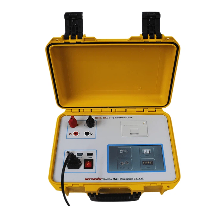
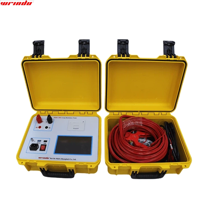
The Loop Resistance Tester follows the relevant standards of the International Electrotechnical Commission (IEC) and my country’s power industry standard DL/T845.4-2004. It is built based on our company’s deep accumulation and R&D advantages in power testing technology. It is a professional high-precision digital switch detection instrument.
The instrument adopts high-frequency, high-power constant current switching power supply technology. Based on Ohm’s law, it applies a stable high-frequency, high-power constant current source to the object under test, accurately measures the loop voltage drop, and realizes accurate measurement of micro-ohm contact resistance. The core technology lies in the precise regulation of the constant current source and the high-sensitivity detection of weak voltage signals to ensure that the measurement results are accurate and reliable.
Regarding application, the RDHL-100A Loop Resistance Tester has a wide range of applicability. It can be used to measure the contact resistance of various high and low-voltage switchgear, accurately detect the contact resistance of closed contacts, and provide a key basis for switch maintenance and repair; it is suitable for contactors, relays, and other electrical circuit resistance measurement, which helps performance detection and fault diagnosis; it is also accurate in measuring the contact resistance of cable and wire connection parts and welds, and can effectively detect abnormal resistance caused by poor connection or welding defects to ensure electrical performance.
CHARACTERISTIC
• With reverse EMF protection function, it can effectively resist the impact of reverse EMF on the instrument. The equipment provides multiple protections during the test, such as disconnection, power failure, and power overheat protection, and is equipped with a synchronous sound alarm system to ensure the safe operation of the equipment.
• The introduction of intelligent power management technology allows the instrument to always work in the lowest power mode, effectively saving energy and reducing heat generation.
• Provides higher output voltage and a wide measurement range to meet various test needs.
• The test current is provided by a high-precision, high-current constant current power supply, eliminating manual adjustment and ensuring fast and accurate test results.
• The four-terminal wiring method is adopted to minimize the influence of test line resistance on the measurement results and ensure test accuracy.
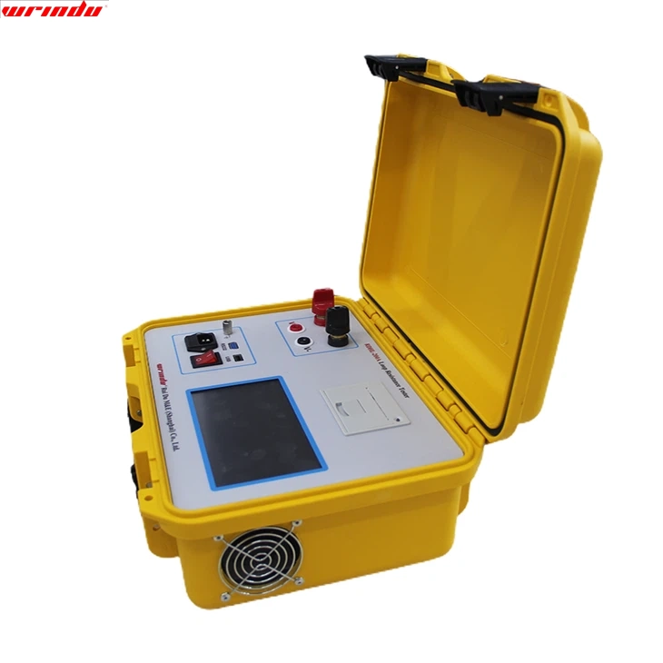
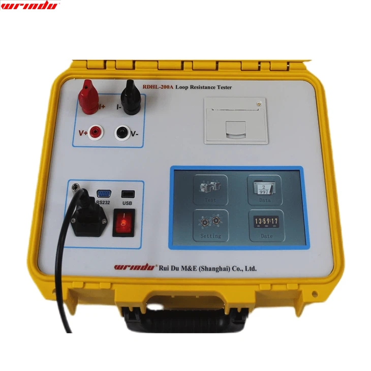
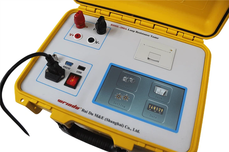
• The Loop Resistance Tester is equipped with a seven-inch high-brightness touch color LCD screen; it can still display clearly under intense light, fully supports touch operation, and provides a convenient use experience.
• The built-in perpetual calendar clock function and power-off storage can automatically save 1,000 sets of test data, making checking historical records at any time convenient.
• It supports Bluetooth, RS232, and USB interfaces, enabling communication with a computer and data storage to a USB flash drive, providing more data transmission and storage options.
For more information about circuit breaker testing equipment, please click More.
To request the latest quotes, please click Contact Us.
FAQ
Q: How do you test loop resistance?
A: The most effective method for loop resistance testing involves specialized tools like the legacy ‘LRT’ or MK Test Systems range. These tools use clamps to inject a current into the loop, measuring it as it flows through. This technique ensures accurate and efficient loop resistance assessment in electrical circuits.
Q: What instrument is used to test the earth loop impedance?
A: Earth loop testers are instruments designed to trace the path of earth loop impedance in an electrical system. They help users assess whether the impedance path is adequate for triggering protective measures in the system before potential issues occur.
Q: What happens if the earth fault loop impedance is too high?
A: When the earth fault loop impedance is excessively high, it results in inadequate fault current, potentially causing protective devices like circuit breakers to trip slowly or not activate at all. On the other hand, if the impedance is excessively low, an abundance of fault currents may cause the protective device to trip too rapidly, posing a potential hazard. Maintaining an optimal earth fault loop impedance is crucial for ensuring the reliable and safe operation of protective devices in electrical systems.

