OVERVIEW
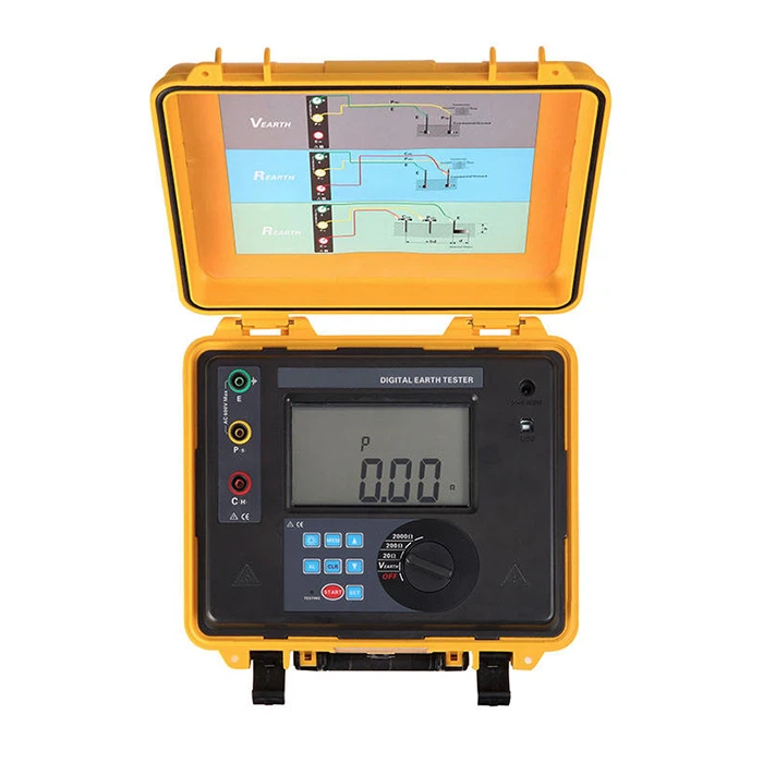
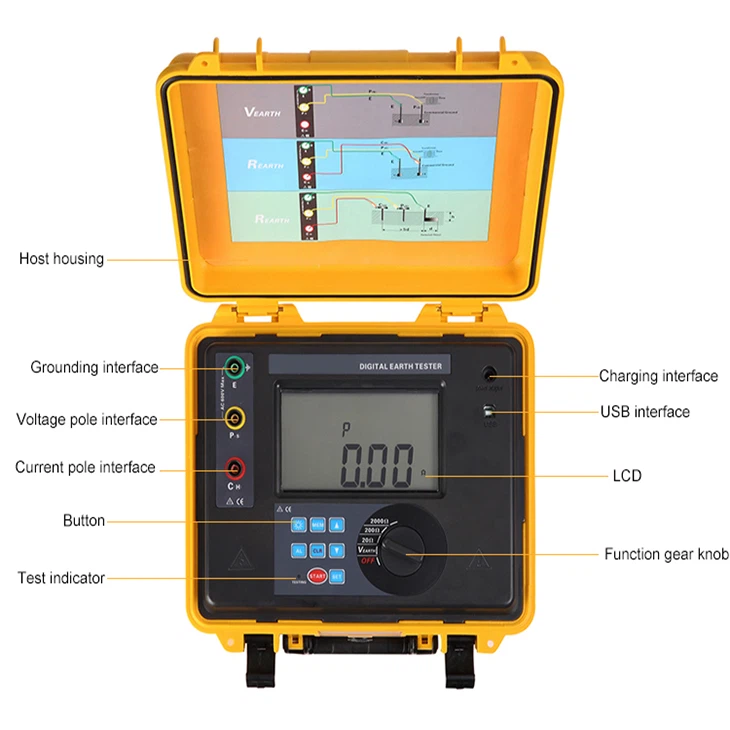
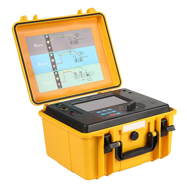
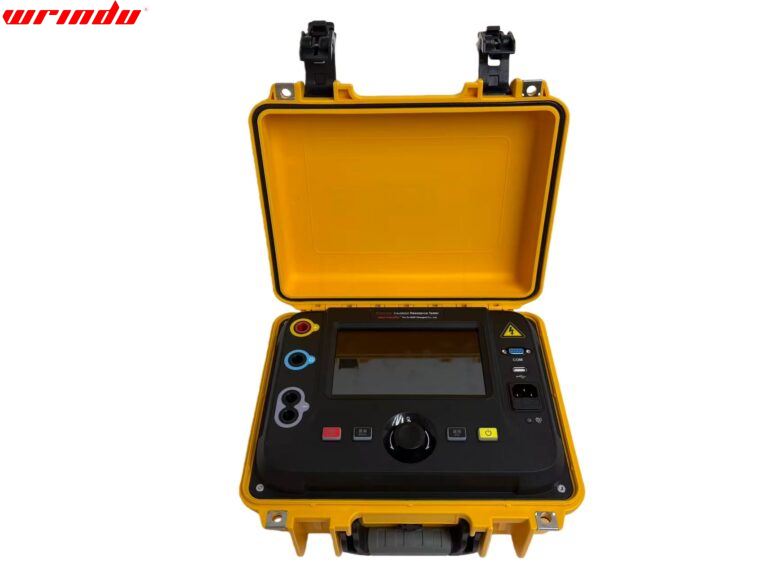
Our company’s digital ground resistance tester is designed for on-site ground resistance measurement. It integrates digital and microprocessing technology and can accurately measure ground resistance using precision 3-wire or simple 2-wire methods. The instrument has excellent wire resistance calibration characteristics, anti-interference solid performance, and excellent environmental adaptability, which effectively guarantees high precision, stability, and reliability in long-term measurement operations. Among them, the unique wire resistance calibration function of the new ground resistance tester shows higher accuracy for on-site low-value ground resistance measurement, effectively avoiding errors caused by changes in wire resistance due to long-term use of the test line and preventing deviations caused by incomplete insertion or poor contact between the test line and the instrument interface, as well as errors caused by users replacing or extending the test line. This product has extensive applications in ground resistance measurement in power, telecommunications, meteorology, construction, lightning protection, and industrial electrical equipment.
CHARACTERISTIC
- 1. Provides dedicated line resistance calibration function
- 2. It has an LCD, supports white backlight, and an intuitive bar graph display function.
- 3. Supports storage of 400 sets of data
- 4. It can display maximum, minimum, and average values
- 5. With historical data reading and review function
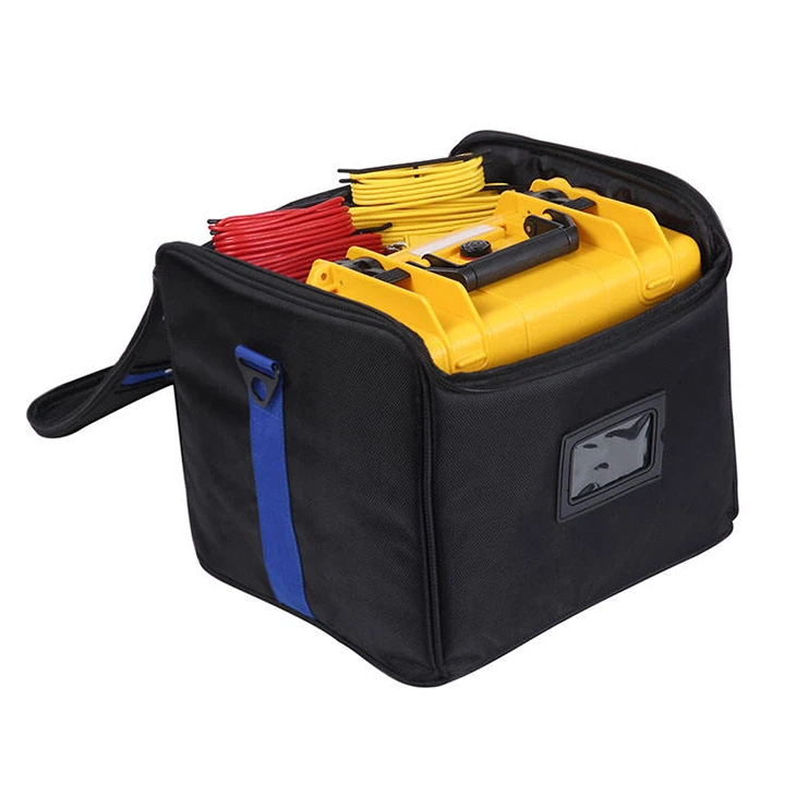
- 6. The digital ground resistance tester shell adopts a sturdy, waterproof protective box design with anti-collision, anti-fall, and waterproof functions.
For more information about ground resistance testers, please click More.
To request the latest quotes, please click Contact Us.
FAQ
Q: How do you test earth ground resistance?
A:
1. Fall-of-Potential Test:
Procedure: Equilateral triangle stakes, measure voltage drop.
Calculation: R = Voltage Drop / Current.
2. Four-Pole Testing:
Enhancement: Adds an extra potential electrode.
3. Clamp-On Testing:
Tool: Specialized clamp-on tester.
Method: Measures magnetic field.
4. Wenner 4-Wire Method:
Setup: Four equally spaced electrodes.
5. Soil Resistivity Testing:
Objective: Evaluate soil resistivity for grounding system design.
Q: What is the earth resistance tester?
A: A digital ground resistance tester is a tool that measures how well electrical grounding systems can dissipate currents into the ground, ensuring safety and preventing electrical hazards. It typically uses the fall-of-potential method, involves multiple electrodes, and is portable and digital for accurate readings. Regular testing is essential for maintaining a reliable grounding system.
Q: What is an acceptable earth ground resistance value?
A: The acceptable earth ground resistance value isn’t universally standardized. Generally:
– NFPA and IEEE recommend aiming for 5.0 ohms or less.
– NEC suggests ensuring system impedance to ground is below 25 ohms (as per NEC 250.56).
Specific industry guidelines and local regulations might influence the acceptable resistance value.

