
SFRA Trace Comparison: Reading Deviation Without Overreading It
Send your test requirement — get a tailored solution and a quote within one working day.
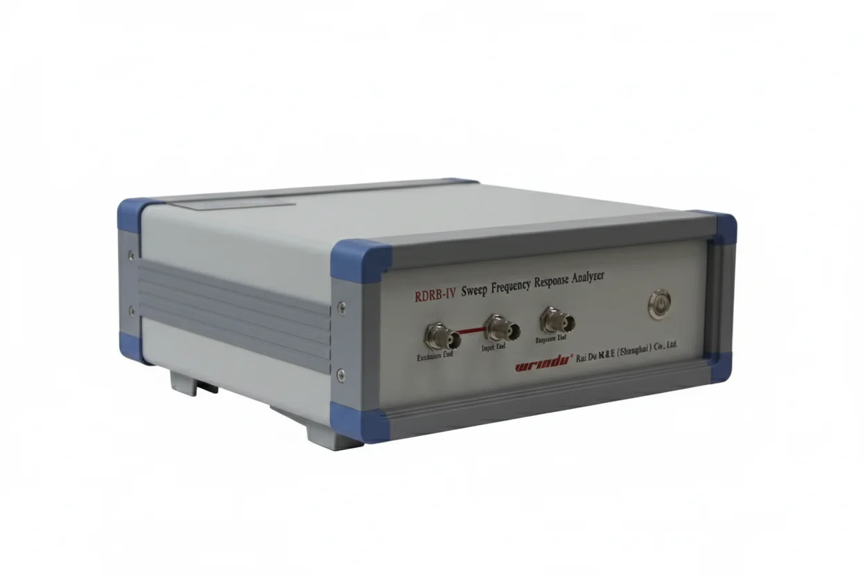
What SFRA compares
SFRA measures the impedance or the transfer response of a winding across a wide frequency band and plots magnitude and phase against frequency, typically on a logarithmic axis. The response is the fingerprint of the electrical network formed by the winding turns, the insulation between them, the core and the internal leads. Change the geometry of that network, and the curve changes in a characteristic way. What makes the method useful in practice is that it is sensitive to mechanical displacement that electrical tests miss. A winding that has been axially displaced by a through-fault, a set of turns that has shifted radially, a lead that has moved against the tank wall, a core that has lost its clamping pressure: these conditions can leave ratio, resistance and even insulation readings unchanged, because the electrical path is intact. The geometry is not, and the frequency response sees geometry. The measurement itself is standardised in IEC 60076-18, which defines the frequency range, the connection configurations and the way results should be presented. It deliberately stops short of defining pass or fail limits, because the reference for a valid comparison is the same transformer at an earlier time, not a generic curve.Deviation bands and how to read them
Reading a trace starts with dividing the frequency axis into regions rather than looking at the curve as a whole. Each region is dominated by a different part of the transformer, so a deviation means something different depending on where it appears. Interpreting the curve without that division is how healthy transformers end up scheduled for unnecessary outages. The low frequency region, broadly up to a few kilohertz, is dominated by the core and the magnetising behaviour of the winding. Deviations here often reflect residual magnetisation from earlier direct current testing, a different core state, or a different tap position rather than damage. This is the region most commonly overread, and the first question to ask is what electrical test was performed immediately before the sweep. The mid frequency region is where winding geometry dominates, and it is the region that carries the most diagnostic weight. Axial displacement moves the resonant peaks in this band, and radial deformation changes their amplitude and spacing. The high frequency region is dominated by the internal leads, the bushing capacitance and, increasingly, by the measurement setup and the equipment in the substation around the transformer.| Frequency region | Dominated by | Typical cause of a deviation | First check before escalating |
|---|---|---|---|
| Low, up to a few kHz | Core and magnetising behaviour | Residual magnetisation, tap position, core state | What DC test preceded the sweep, and at what tap was the reference taken |
| Mid, geometry band | Winding inductance and capacitance distribution | Axial displacement, radial deformation, turn movement | Repeatability of the sweep and identity of the connection configuration |
| High, above roughly 1 MHz | Internal leads, bushings, setup | Lead dressing, grounding, neighbouring equipment | Was the lead dress and grounding identical to the reference test |
Which faults each frequency region indicates
Axial displacement of a winding, typically caused by the electromagnetic forces of a close-in short circuit, moves the winding relative to its normal position and changes the capacitive coupling to the adjacent winding and to the core. The result is a shift in the mid frequency resonances, and the shift direction is comparable between phases, which makes a three-phase overlay a fast way to see it. Radial deformation, where a winding section bulges or flattens, changes the distance between turns within the same winding. The effect is strongest in the mid frequency band but appears as a change in peak amplitude and damping rather than as a clean lateral shift. It is the change most often confused with a manufacturing difference when a sister unit is used as the reference. Core-related problems, including a shorted core limb, loss of core clamping pressure and core grounding changes, typically show up in the low frequency region and often in the shape of the first resonances. A core ground fault can also be visible in the high frequency region as a change in the overall response level, which is one reason the core ground connection should be documented as part of the test setup. Bushing and lead problems sit at the top of the range. A changed bushing capacitance, a repaired lead connection or a different length of test lead all produce high frequency deviation, which is exactly why that region is the weakest basis for condemning a winding.False positives: lead placement and grounding
The single most common cause of a false positive is a change in the measurement setup between the reference test and the follow-up test. Frequency response is measured at high frequency, and at high frequency the test leads are not wires, they are distributed elements with their own inductance and capacitance. Move a lead by a few centimetres and the top of the curve moves with it. Grounding is the second cause. The tank grounding point, the core ground connection and the grounding of the measuring instrument all affect the current return path. A test performed with the transformer grounded through a different point than the reference test can show a deviation across a wide band that has no physical counterpart inside the transformer. Other recurring false positives are a sweep taken immediately after a direct current resistance test while the core is still magnetised, a sweep taken at a different tap position from the reference, and a sweep taken with the bushings still connected to other equipment. Each of these has a specific remedy, and all four are eliminated by the same discipline: record the setup, then reproduce it.Comparing against a fingerprint versus a sister unit
A fingerprint comparison measures the same transformer at two points in time. Its strength is that everything except the winding condition is held constant: design, materials, core, instruments and, if the setup is reproduced, the measurement configuration. Where a fingerprint exists, it is the reference to use, and no sister unit comparison can substitute for it. A sister unit comparison measures two nominally identical transformers. Its weakness is that nominally identical units are not electrically identical. Manufacturing tolerances in winding geometry, differences in lead routing, and even differences in the amount of core clamping pressure produce measurable differences between healthy units. A sister unit comparison can confirm that a transformer is broadly normal, and it can reveal a deviation that is much larger than the unit-to-unit spread, but it cannot resolve small changes. Where only a sister unit is available, the practical approach is to compare all three phases of the suspect unit against each other first, since a deformation usually affects one phase more than the others, and then against the sister unit as a secondary check. That ordering reduces the chance of condemning a healthy unit because it happens to differ from its neighbour in a way that was always present.When a repeat test settles the question
A repeat test settles the question more often than any interpretation technique. If the second sweep, taken with the setup reproduced from the reference conditions, reproduces the original trace, the deviation came from the setup. If it reproduces the deviation, the deviation is real and belongs to the transformer. That is a binary outcome, and it costs one additional sweep rather than an outage. For the repeat to be meaningful, the earlier conditions have to be known. That means the reference record should identify the tap position, the winding connection configuration, the lead arrangement, the grounding points and the instrument used. When a programme is set up with those fields, the repeat is routine. When they are missing, the repeat produces a third trace rather than an answer. A repeat also separates transient from permanent causes. Residual magnetisation from a preceding DC test, a winding that has not fully settled at its operating temperature, and a temporary ground connection are all transient and will not reproduce on a clean repeat within a short interval.Recording conditions for repeatability
A usable SFRA record contains the transformer identification and tap position, the winding and connection configuration, the sweep range and the number of points, the instrument type and serial number, the lead set used, a photograph or sketch of the lead arrangement, the grounding points, and the raw data files. The raw files matter because interpretation is done later and partly by software; a printed curve cannot be re-processed. The record should also note what preceded the test. A sweep taken after a resistance test on a magnetised core is not wrong, but it is not directly comparable with a sweep taken on a demagnetised core, and the record needs to say so. Where a comparison programme spans several years, that condition note is often the difference between a deviation that is understood and a deviation that triggers an investigation.Escalation criteria before condemning a winding
Escalation should require a reproducible deviation in the geometry-dominated region, with the measurement setup verified and no alternative explanation available. That is a higher bar than most site conversations assume, and it exists because the consequences of the two errors are not symmetric: missing a deformed winding risks a failure, while condemning a healthy one costs an outage, a replacement decision and a loss of confidence in the test method itself. The step before condemnation is normally to combine SFRA with other evidence. A winding that has been displaced by a through-fault usually shows a change in short-circuit reactance as well, and a deformation that affects the insulation may show up in dissolved gas analysis. Bringing those results alongside the sweep is what turns a curve into a defensible engineering conclusion, and the transformer rating definitions the conclusion refers back to are set out in IEC 60076-3. Where no fingerprint exists and the sister comparison is ambiguous, a reasonable escalation is to re-measure at the next planned outage, confirm that the trace is stable, and use the current sweep as the fingerprint for all future comparisons. That decision is not a failure to diagnose; it converts an unusable history into a usable one at no additional cost.
Comparing traces recorded by different instruments
Mixing instruments introduces differences that are independent of the transformer. Different analysers inject different signal amplitudes, use different source and receiver impedances and apply different filtering, and the resulting differences appear at the top of the frequency range where the setup dominates. Two instruments measuring a healthy transformer can disagree by more than a genuine fault would produce. The practical rule is to keep one instrument for the whole life of a comparison series. Where that is impossible because a fleet is spread across several substations, the transition between instruments should be handled as a controlled test: measure the same transformer with both instruments, record the difference, and treat that difference as an offset for every later comparison between them. Where instruments differ, prioritise the mid frequency geometry band for interpretation, and treat high frequency differences as instrumentation until proven otherwise. Independent asset management research, such as the transformer condition programme published by EPRI, follows the same logic, and the analyser documentation from the instrument manufacturers is the reference for the specific signal levels and connection options of a given model. Two further references help when a comparison programme is being written. Technical notes from instrument suppliers such as OMICRON describe how electrical interference affects a sweep and how to recognise it, and applied transformer diagnostic material such as the case work published by Transformer Consultants shows how a deviation is corroborated before a winding verdict is issued. The wider research picture on condition assessment is coordinated through CIGRE study committees.FAQ
How large a deviation is significant in an SFRA trace?
There is no single number, which is why the method is written around frequency regions rather than one tolerance. The low frequency region, below roughly 2 kHz, is dominated by the core and is sensitive to magnetisation state and to test conditions. Mid frequencies relate to winding geometry, and high frequencies above roughly 1 MHz relate to the leads and to the measurement setup itself.
Can SFRA results be compared between two different instruments?
Only with care. Different analysers inject different signal levels, use different lead sets and may terminate the winding differently, all of which show up in the trace, most visibly at high frequency. If instruments must be mixed, keep the same instrument for all measurements on a given transformer so the comparison stays internal to one setup.
What is the difference between comparing against a fingerprint and a sister unit?
A fingerprint is the same transformer measured before and after an event, so the comparison isolates change in that unit. A sister unit comparison compares two nominally identical transformers, so a deviation may reflect manufacturing tolerance rather than damage. Fingerprint comparison is stronger evidence in every case where a baseline exists.
Does an SFRA deviation mean the transformer must be taken out of service?
Not on its own. A deviation is a question, not a verdict. The next step is to confirm the measurement conditions, repeat the sweep, and check whether a physical cause such as a bushing tap, a lead position or a grounding change explains the difference. Outages are justified when the deviation is reproducible and no measurement cause can be found.
Why does the same transformer sometimes produce a different trace in the afternoon?
High frequency behaviour is sensitive to how the leads are dressed, how the tank is grounded and whether nearby equipment has changed. A trace taken with the test leads in a different position is not a repeat of the earlier measurement. Recording lead placement and grounding as part of the test record is what makes a repeat measurement comparable.
Related articles
 SF6 Leak Detector Sensitivity: Select a Method for the Inspection TaskKnowledge
 Cable Fault Locator Selection for Urban Networks: Routes, Noise and AccessKnowledge
 Substation Battery Load Bank Sizing: Duty, Voltage Range and Heat RejectionKnowledge
 CT Polarity, Ratio and Burden Testing: Find Wiring and Loading ErrorsKnowledge