Relay protection testing
RuiDu Mechanical: Your Reliable Relay Protection Tester Supplier!
RuiDu Mechanical and Electrical (Shanghai) Co., Ltd. is a leading global power testing equipment manufacturer and system solution provider. Our company was established in 2014. Our main products are substation transformers, high-voltage switches, transformers, lightning arresters, batteries, cable faults, relay protection, insulation withstand voltage, transformer oil injection equipment, etc. Our factory covering an area of more than 50,000 square meters, 6 product production lines and more than 200 employees, selling the products to more than 120 countries and regions. In addition, we support high-volume production, calibrate and test instruments at the point of sale, providing repair instructions for these products.
Rich Experienced
Our team has more than 10 years of experience in the industry, providing customers with compliant, high-quality equipment, and developing friendly cooperation with partners such as Kenya Power, UETCL, TCN, EVN, PLN, NGCP, CFE.
Wide Product Range
Our broad product offering includes digital multimeters, power analyzers, thermal imaging cameras, insulation resistance testers, accessories and integrated test tools. These test devices can be easily integrated into a variety of electrical and electromechanical systems.
Guaranteed Quality
Our production workshops are professionally assessed, developed and validated, equipped with a range of analytical instruments and all products have international ISO 9000 series, IEC and CE certifications.
Customized Service
According to your usage needs, our team is online 24/7 to provide you with detailed consultation and after-sales service, and provide OEM and ODM customized products.

What is Relay Protection Tester?
A protective relay test includes the review of protective devices in a system, for the safe operation of power supply networks. The Relay Tester assists in the inspection, installation, and repair of assigned electro-mechanical controls and equipment systems. The professionals have to assemble the equipment in the right position to operate test equipment and related instruments, complete test forms and enter test results. The testers are used in major substation or plant construction projects, to cross check the control and protective circuit diagrams to ensure they are as per the industry standards.
Features of Relay Protection Tester
Multi-functional
Our relay protection testers are suitable for performing a variety of test requirements for analog testing, with transient, component, scheme, energy meter and sensor testing capabilities.
Strict Quality
These testers comply with several important industry standards, with traceability to NIST standards and EMC immunity standards, EN and IEC certifications, and provide accurate results.
Clear Data
They can be used in conjunction with a tablet to control all sources and perform protection tests. Their displays provide data to the operator, including active voltage, current amplitude and phase values.
High Precision
These test equipment applications include conventional, electromechanical, electronic and microprocessor relays, with multiple AC/DC amplifier capacities, high-level analog sources and low-level analog sources, with an accuracy of ± 0.25°.
Application of Relay Protection Tester
Safety Assurance
In many applications, such as power distribution and industrial automation, relays play a critical role in controlling electrical currents. So its test applies to all varieties of electric power systems, for example by energy suppliers in the production, but also in the distribution and transmission. Similarly, this also applies to areas such as ship
Reliability Enhancement
Protective devices and periodic reviews are very important above all for the safe operation of power supply networks. The protective relay test refers to the protective relay. The proper operation of a protective relay has to be monitored over its entire life or period of operation. This ranges from initial development to production and on-site commissioning to regular testing. For example, they are vital in critical systems like emergency shutdowns, aviation, and medical equipment.
Preventive Maintenance
To ensure that a protective relay in the given parameters is safe and reliable, the relay must be checked before commissioning on various criteria. Be tested this fault conditions, shifts or steady-state operating conditions, logic diagrams, and other things. Since, in normal operation of the system is not the protective relay used routine tests to be carried out at regular time intervals are required. This routine tests ensure continuous protection of the system by the relay and also extend the life of the relay.

Types of Relay Protection Tester
Primary Injection Test Systems
Primary injection testing, as opposed to the secondary injection test, is the only way to prove correct installation and operation of the whole protection chain, as the test involves the entire circuit: current transformer primary and secondary windings, relays, trip and alarm circuits, circuit breakers, and all wiring.
Relay Test System
It is a tool that tests protection relays with different functions. These tests are important for the safe operation of electrical systems. They can help identify and correct problems before they cause a system failure.
Secondary Current Injection Kit
Secondary current injection testing is an electrical compliance testing method in which a strong current is inserted directly into a trip relay to test a circuit breaker. Current injection is a testing process used to test the insulation of an electrical safeguard like a circuit breaker.
Megger Low Level Adaptor
The Megger low level adaptor has been designed to filter the low-level outputs from the latest version of voltage/current generators. In some mode, the current channels will convert from a current source to a millivolt source. The adapter can trigger the charging process by selecting the appropriate Proximity Pilot (PP) and Control Pilot (CP) states. It can also determine if dangerous voltages are present on the PE.
Megger Relay Test System
The Megger relay test system is a multipurpose, lightweight, field portable test set capable of testing a wide variety of electromechanical, solid state, and microprocessor-based protective relays, motor overload relays, and similar protective devices.
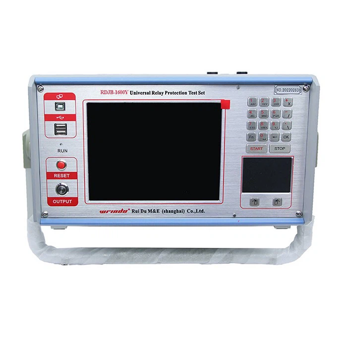
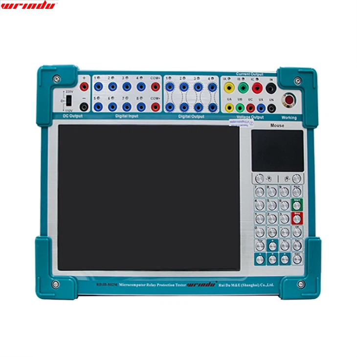
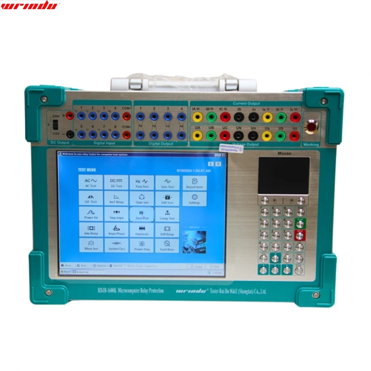
Key Components of Relay Tester
Front Panel of Relay Tester
●TFT LCD display
●Track ball mouse, left and right key of track ball mouse
●Faceplate optimized keyboard
●Power supply switch
●USB interface: It can be connected with external equipment like mouse, keyboard, flash disk, printer, etc
●Net terminal: It can be connected with outer PC to doing test
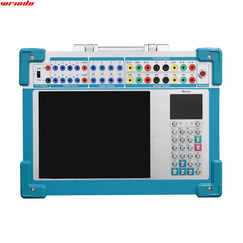
Rear Panel of Relay Tester
●Auxiliary DC power supply output: It can be switched to 110V or 220V, and can be used as on-the-spot testing power supply
●Voltage output fuse
●AC operational power supply socket
●PPS
●Communication port with outside GPS device
●Wind outlet of cool fan
Different Methods of Relay Testing
Preparing Your Relay
(1)Do a Basic Visual Inspection of the Relay.
Many relays have a clear plastic shell containing the coil and contacts. Visible damage (melting, blackening, etc) will help narrow down the issue. Most modern relays have an LED to tell you if they are in the active state (ON). If that light is off and you’ve got control voltage to the relay or coil terminals then you can safely assume that relay is bad.
(2)Disconnect the Power Source.
Any electrical work should be done with all power sources disconnected, including batteries and line voltage. Be especially mindful of capacitors in the circuit, as they can hold a charge for a considerable length of time after removing the power source. Do not short capacitor terminals to discharge. It is best to check your local laws before performing any electrical work, and if you feel unsafe, leave it to the professionals. Extra low voltage work typically will not fall under this requirement, but it’s still important to be safe.
(3)Consult the Relay Schematic or Data Sheet.
Relays have fairly standard pin configurations, but it is best to search for the data sheets to find out more about the number of pins from the manufacturer, if available. Typically, these will be printed on the relay.
Information on current and voltage ratings, pin configurations, and other information is sometimes available in the datasheets will be invaluable in testing, and eliminate most errors associated with testing. Testing pins randomly without knowing the pin configuration is possible, but if the relay is damaged, results may be unpredictable. Some relays, depending on their size, may also have this information printed directly on the body of the relay as well.
Testing Coil Relays
(1)Determine the Coil Requirements of the Relay.
The manufacturer’s part number should be listed on the case of the relay. Look up the applicable data sheet and determine the voltage and current requirements of the control coil. This also may be printed on the case of larger relays.
(2)Find Out If the Control Coil is Diode Protected.
A diode around the pole is often used to protect the logic circuitry from damage due to noise spikes. The diode will be shown on drawings as a triangle with a bar across one corner of the triangle. The bar will be connected to the input, or positive connection, of the control coil.
(3)Assess the Contact Configuration of the Relay.
This will also be available from the manufacturer’s data sheet, or may be printed on the case of larger relays. Relays may have one or more poles, indicated in drawings by a single line switch connected to a pin of the relay. Each pole may have a normally open (NO) and or normally closed (NC) contact. The drawings will indicate these contacts as connections with a pin on the relay. The relay drawings will show each pole as either touching the pin, indicating a NC contact, or not touching the pin, indicating a NO contact.
(4)Test the De-energized Condition of the Relay Contacts.
Use a digital multimeter (DMM) to test the resistance between each pole of the relay and the corresponding NC and NO contacts for that pole. All NC contacts should read 0 ohms to the corresponding pole. All NO contacts should read infinite resistance to the corresponding pole.
(5)Energize the Relay.
Use an independent voltage source appropriate for the rating of the relay coil. If the relay coil is diode protected, make sure that the independent voltage source is connected with the proper polarity. Listen for a click when the relay is energized.
(6)Check the Energized Condition of the Relay Contacts.
Use a digital multimeter (DMM) to test the resistance between each pole of the relay and the corresponding NC and NO contacts for that pole. All NC contacts should read infinite resistance to the corresponding pole. All NO contacts should read 0 ohms to the corresponding pole.
Testing Solid-State Relays
(1)Use an Ohmmeter to Check Solid-state Relays.
When solid-state relays start to short, they will almost always fail. Solid-state relays should be checked with an ohmmeter across the normally open (N.O.) terminals when control power is off. The relays should be open, switched to OL, and closed (0.2 , the internal resistance of the ohmmeter) when control power is applied.
(2)Use a Multi-Meter in Diode-test Mode to Confirm Your Findings.
You can further confirm that the relay is bad by taking a multi-meter, put it in diode test and checking across A1(+) and A2(-). The meter will apply a small voltage to make the semiconductor conduct and read that voltage on the screen. This will check the (typically NPN) transistor from the base(P) to the… emitter.
If its bad, the meter will read 0 or OL, but if the relay is good it will read 0.7 for a silicon transistor (which almost all of them are) or 0.5 for a germanium transistor (which are relatively rare but not unheard of).
(3)Keep SSR cool.
Solid-state relays are easy to troubleshoot, cheap to replace and last a long time if they stay cool. Typically, new relays come in DIN rail packages and block mountings. There is also a special type of relay called an SCR that comes in two flavors for heating wires and IR lamps and ovens, usually for exquisite process temperature control. This is basically a fast switch on a much faster switch that can turn off and on, which fail often due to temperature fluctuations.
How to Perform a Relay Test?
(1)Performing a relay test may involve various steps depending on the test method, equipment, and relay. Generally, you should prepare a test plan and procedure that outlines the test objectives, criteria, parameters, and scenarios.
(2)Then, you must isolate the relay from the power system and disconnect any unwanted connections or loads.
(3)After connecting the testing equipment to the relay terminals and/or the primary sensors, set the relay settings and testing equipment parameters according to the test plan.
(4)Subsequently, apply the input signals and observe the output actions of the relay and testing equipment. Make sure to record the test results and compare them with the expected values and accuracy specifications. Analyze any errors, deviations, or anomalies that may arise from this comparison.
(5)Finally, report your findings and recommendations while documenting the entire process and outcomes.
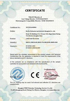
Certificate Photo


Factory Photo
FAQ
Q: What is the protective relay function test?
A: The functional tests consist of using the adequate inputs to the protection relay under test and measuring the performance to discover if it meets the specification. They are typically completed under controlled environmental conditions.
Q: What is the relay function test system?
A: The Relay Functional Test is a system that allows validation of all the relays commutation phases and control of their own consumption. This system ensures the wiring delivery with all the relays accurately working.
Q: How often should protection relays be tested?
A: Every 2 years. Due to their critical role in the power system, protective relays should undergo acceptance testing before being placed in service and periodic testing thereafter to ensure reliable performance. In a typical industrial application, testing should be conducted at least every 2 years in accordance with NFPA 70B.
Q: What are the different types of testing for relays?
A: Tests vary based on the relay technology, but may include: Visual and mechanical inspection. Insulation resistance measurements. Secondary injection tests.
Q: What is the easiest way to test a relay?
A: To test this, leave your multimeter on the ohms setting and measure the resistance between the switch pins. On a four-pin relay, these are typically labeled 87 and 30. You should see no resistance at all between these pins. If you do, that means that the pins are stuck closed and the relay is bad.
Q: What are the three main types of relays?
A: There are a variety of different types of relays for a variety of different uses. The three most commonly used types are electromechanical relays (EMR), solid-state relays (SSR), and Reed relays.
Q: How much resistance should a relay have?
A: Between 50 ohms and 200 ohms. The electrical resistance (impedance) of the coil is vary and is different depending upon the manufacturer of the relay as well as relay’s type, but in general a typical value should be expected between 50 ohms and 200 ohms. Input current typically is in the range between 100 mA and 150 mA.
Q: What causes a relay to fail?
A: The two most common failure mechanisms of relays are contamination and mechanical wear of the internal switching elements discussed as follows: a. Contamination is a major cause of early life failures.
Q: Can an electrical relay go bad?
A: Many electrical components in a vehicle or machine are controlled by a relay. So if a component isn’t working because electricity isn’t getting to it, there is a possibility the relay may be faulty. But determining whether or not a relay is defective requires a little basic investigation. Here’s how to go about it.
Q: How many years do relays last?
A: Relays generally last around 200,000 cycles on average (roughly 18+ months depending on usage, firing temperature, and firing profile), but can fail long before or long after without any explanation.
Q: Can a car relay be tested?
A: If it is still not working, it may be necessary to use a test light or multimeter to double-check your incoming and outgoing power, ground, and continuity, but testing the relay itself may be as simple as turning the ignition or auxiliary switch on and off and listening for a click.
Q: How do I identify a relay?
Q: How many amps is a relay rated for?
A: These rating indicate how much power can be switched through the relays. This does not necessarily tell you what the limits of the relay are. For instance, a 5 Amp relay rated at 125VAC can also switch 2.5 Amps at 250VAC. Similarly, a 5 Amp relay rated at 24VDC can switch 2.5 Amps at 48VDC, or even 10 Amps at 12VDC.
Q: How many volts should a relay have?
A: Generally a relay coil is rated by voltage, not current. If it is a relay with a 12 volt coil, it will operate at approximately 12 volts. Unless the coil is damaged, it will not draw too much current as long as the emf applied to it is approximately 12 volts, perhaps as low as 9 volts or as high as 16 volts.
Q: Which relay is mostly used?
A: Electromagnetic relay is the simplest, oldest and most widely used relay. Its basic components are coils, magnetic cores, armatures, springs and contacts. The magnetic system is used to convert the input current into the mechanical power required for contact closure.
Q: What appliances use relays?
A: Relays make it possible to start up electric and electronic gadgets and appliances such as refrigerators, cars, computers, cell phones, furnace fans, industrial equipment, conveyor belts, and more.
Q: How many terminals does a relay have?
Q: What electronics contain relays?
A: Control relays are used in motors, power plants, power supply systems, transistors, and more. Polarized relays are affected by the direction of electrical current. The direction of the current affects the operation of these relays, as the armature inside is permanently magnetized.
Q: Which relay is used for protection?
A: The digital protective relay or numeric relay is a protective relay that uses a microprocessor to analyze power system voltages, currents or other process quantities for detection of faults in an industrial process system. A digital protective relay’s operating principle ranges from simple to complex.
Q: Would a bad relay throw a code?
A: On some vehicles, the engine computer, which is often referred to as the powertrain control module (PCM) monitors the fuel pump relay and its circuit. If the PCM detects a problem, it turns on the check engine light and stores a corresponding diagnostic trouble code (DTC) in its memory.