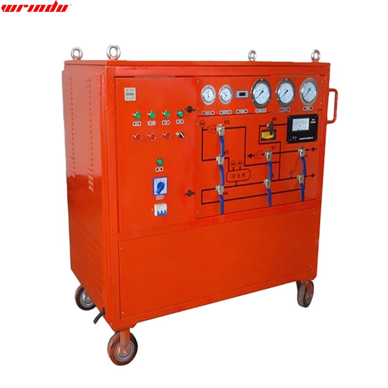

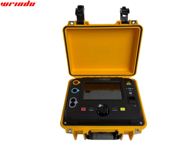
OVERVIEW
As an insulating medium, SF6 gas is non-toxic and nonflammable. Its insulation strength is significantly better than traditional insulating gases, and it has good arc extinguishing performance. It is widely used in SF6 electrical appliances. However, it is expensive and will decompose into toxic components due to arcs, sparks, and corona discharges. Therefore, the gas needs to be recovered using the SF6 recovery system. This device is designed to recover and fill SF6 gas during the manufacture and maintenance of the SF6 recovery system.
CHARACTERISTIC
1. The built-in filtration and adsorption system effectively removes impurities, moisture, decomposition products, and oil from SF6 gas.
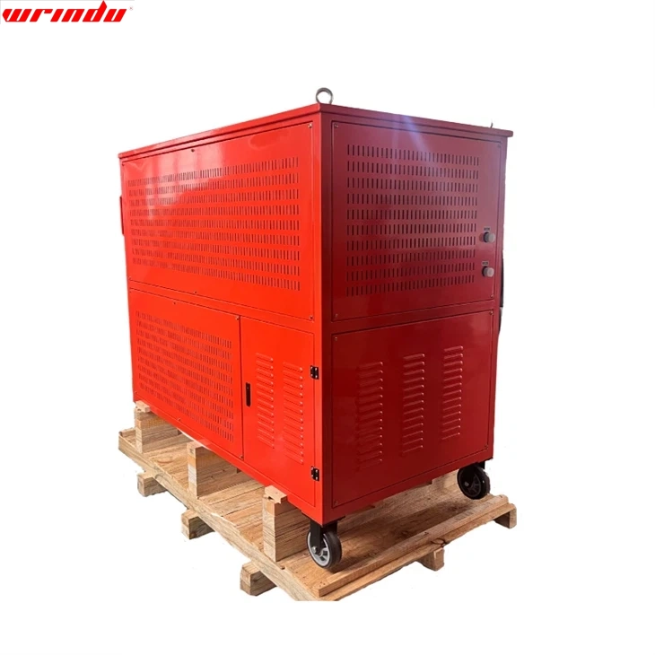
2. Compact, integrated design, easy to move and use.
3. The efficient and maintenance-free filtration system ensures the quality of the recovered SF6 gas.
4. The built-in phase sequence protector can prevent the main engine from reversing due to phase sequence errors at any time.
5. All electrical components are of high-quality brands.
6. High-quality casters protect the floor coating and reduce manual effort when pushing.
7. The SF6 recovery system is air-cooled and does not require an external water source.
8. The built-in temperature protection system can typically work even in an environment of -20°C.
9. Equipped with a drying and heating system to ensure that the desiccant can be regenerated by heating after saturation without the need to replace the desiccant.
10. All ball valves are sealing components with automatic compensation functions.
11. The built-in solenoid valve’s power failure protection function prevents oil reflux caused by the vacuum pump or motor lock’s power failure.
FAQ
Q: How to evacuate SF6 gas?
A: To evacuate SF6 gas, activate the recovery unit’s compressor or vacuum pump. These devices create a vacuum within the circuit breaker’s gas compartment, drawing SF6 gas into the recovery unit for proper handling and storage.
Q: What are the procedures for handling SF6?
A: Using a processing cart (recommended method):
Connect the hose securely to the gas compartment valve and ensure all fittings are correctly tightened.
Activate the vacuum pump to evacuate the hose completely.
Introduce SF6 gas to break the vacuum in the system.
Open the gas compartment valve to allow SF6 gas to flow into the system.
Q: What is the safe handling of SF6 gas?
A: When handling SF6 gas, ensure that no exposed heaters, flames, or equipment could produce arcs nearby. If you detect a rotten egg smell from SF6 gas leakage, evacuate the area immediately unless equipped with proper respiratory protection to avoid exposure.
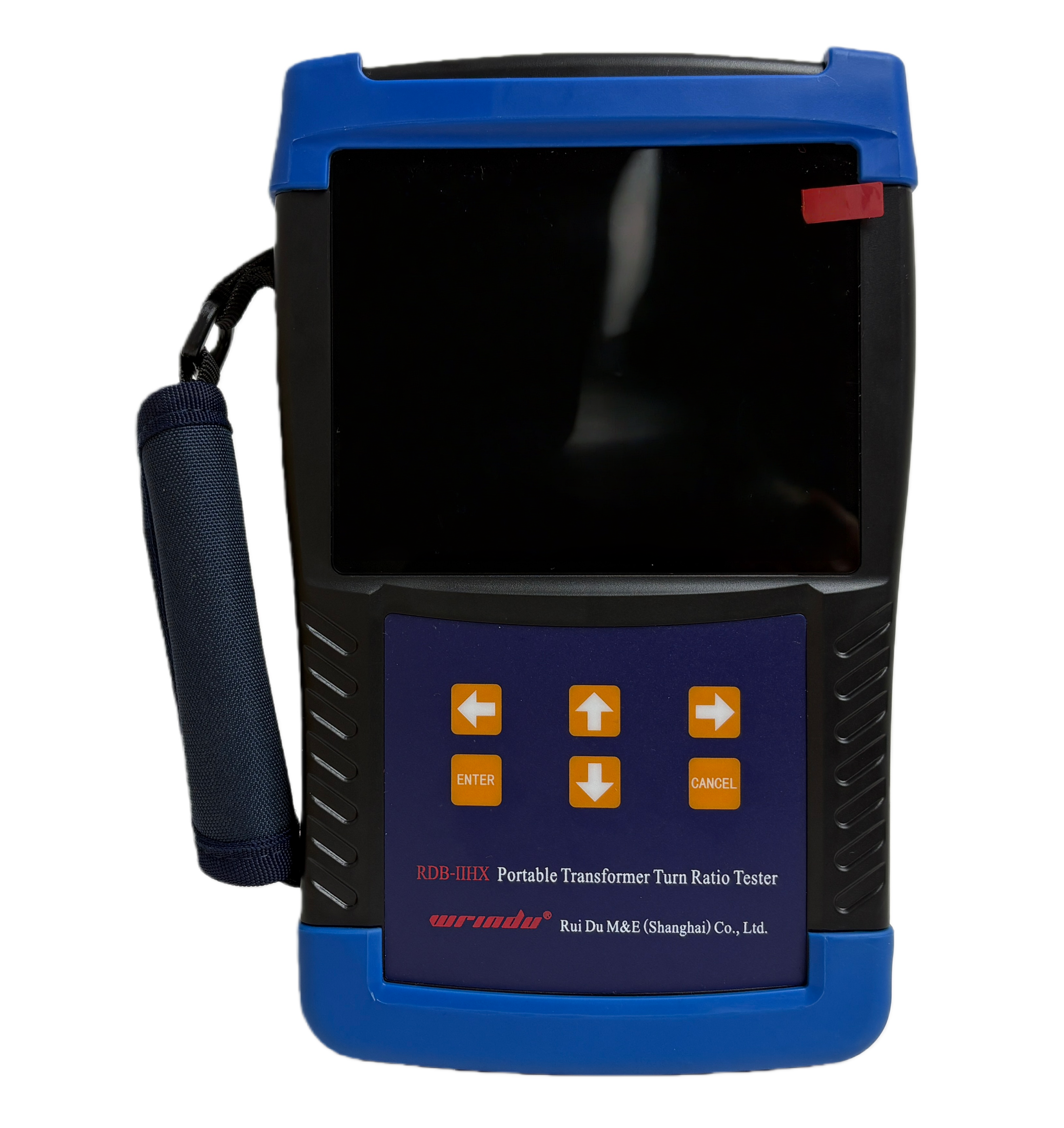
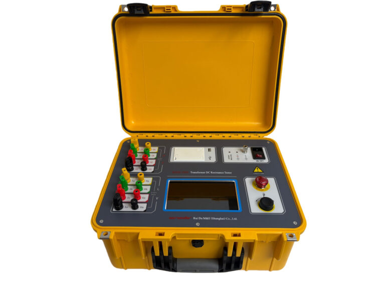
APPLICATION

