
Partial Discharge Measurement Methods: Electrical, Acoustic and UHF Compared
Send your test requirement — get a tailored solution and a quote within one working day.
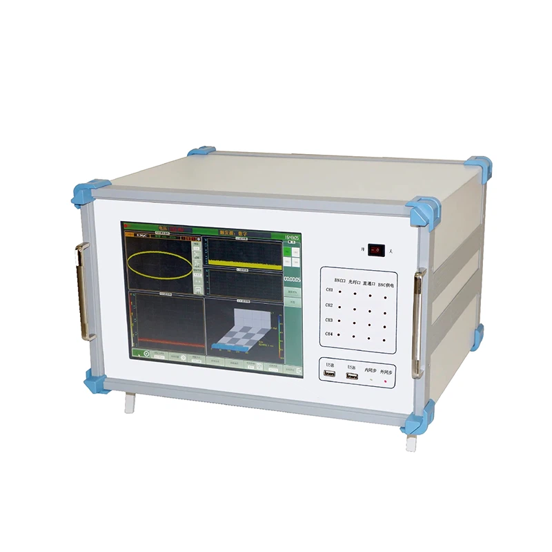
Partial discharge activity is the earliest measurable symptom of most insulation failures, and there are several ways to measure it. Each method responds to a different physical effect, is sensitive to a different class of defect, and fails in a different noise environment. Comparing partial discharge measurement methods on the basis of the defect the asset is likely to develop and the noise the site presents is what produces a usable result.
The conventional framework is defined in IEC 60270, which specifies the electrical method, the quantities to be reported and the way a measurement system is calibrated. The other methods are used alongside it rather than instead of it, because they answer questions the electrical measurement cannot.
Three measurement families, three failure types
The electrical method measures the charge that flows in the circuit as a result of the discharge. It is the conventional technique, it produces a quantity that can be calibrated against an injected charge, and it can be compared with acceptance values written in the same terms.
The acoustic method detects the pressure wave that the discharge generates. Because sound travels through the insulation, the oil and the tank to a sensor placed on the outside, the arrival times at several sensors allow the source to be located. The method’s strength is location rather than magnitude.
The UHF method detects the electromagnetic emission of the discharge in a frequency band where the ambient disturbance is lower than at power frequency. Its strength is sensitivity in gas-insulated equipment, where the discharge site may be some distance from any conventional measurement point and where the electrical method couples poorly.
The failure types differ correspondingly. A void or a delamination inside solid insulation produces discharge that the electrical method detects well. A floating electrode or a loose connection produces discharge that generates a strong acoustic signature. A protrusion on a conductor inside gas-insulated switchgear produces the kind of activity the UHF method is designed for.
Electrical detection: sensitivity and bandwidth
The electrical method couples to the discharge through a measuring impedance or a coupling capacitor connected to the test circuit. The bandwidth of the measuring system determines what it responds to. A narrowband system rejects more noise at the cost of losing information about the pulse shape; a wideband system captures the shape and with it the possibility of separating discharge sources by their waveform.
Calibration is what makes the result comparable. A known charge is injected at the terminals and the response of the whole measuring circuit is recorded, which gives the scale factor for the measurement. Calibrating the circuit rather than the instrument matters, because the coupling capacitor, the connecting leads and the test object all form part of the measuring circuit and all affect the response.
The method’s limitation is that it measures what reaches the terminals. A discharge site deep inside a winding may be attenuated before it arrives, and the measured charge may be much smaller than the charge at the source. That attenuation is why a low reading does not always mean a small defect, and why location methods complement the measurement.
Acoustic and ultrasonic methods in the field
Acoustic detection uses sensors placed on the tank, the enclosure or the surrounding structure. The signal arrives at each sensor after a delay determined by the path length and by the speed of sound in the material, and the differences between arrival times allow the source position to be estimated.
The method’s practical advantages are that it requires no electrical connection to the high-voltage circuit and that it works while the equipment is energised. That makes it suitable for surveying equipment in service without an outage, which is the situation in which partial discharge monitoring is most often wanted.
Its limitations follow from the physics. The signal is attenuated and reflected as it travels, the coupling to the sensor depends on the surface condition, and the interpretation of arrival times assumes a known propagation path. The method gives a position and an indication of activity, and it does not give a charge value that can be compared with an acceptance limit.

UHF for GIS: what it needs to work
The UHF method detects the electromagnetic emission of a discharge in a frequency band typically in the hundreds of megahertz. At those frequencies the ambient disturbance from corona, switching and radio sources is lower than at power frequency, which is what gives the method its sensitivity.
Applying it to gas-insulated switchgear requires access to the inside of the enclosure, either through dedicated UHF couplers fitted at manufacture or through a window or inspection port. The coupling position determines what the sensor can see, because the emission propagates through the enclosure in a way that depends on the geometry and on the presence of spacers and barriers.
Because the coupling is not calibrated to a charge quantity, UHF results are usually expressed relative to a reference and compared against a fingerprint recorded when the equipment was known to be in good condition. That comparison is what the method depends on, and it is the reason a UHF survey is most valuable when a baseline exists. The gas-insulated switchgear requirements that the equipment is tested against are published as IEC 62271-203.
Noise: the constraint that decides the method
The discharge signal is small, and the substation environment produces signals of comparable size. Corona from hardware with sharp edges, switching operations on adjacent circuits, radio and television transmissions, mobile telephones and electronic power supplies all contribute to the noise floor in the frequency band a discharge measurement uses.
What matters is not the sensitivity quoted in a specification but the detection threshold achieved in the actual environment. A system capable of detecting a very small charge in a screened laboratory may be unable to detect ten times that charge on a site where the ambient noise is high.
The practical approach is to qualify the arrangement before relying on it. Measuring the noise floor with the test voltage applied but no known discharge source present establishes what the arrangement can see. Recording that threshold with the result allows a later measurement in a quieter or noisier environment to be interpreted correctly rather than compared directly.
Choosing by asset, environment and evidence needed
| Situation | Primary method | Supporting method | What the combination provides |
|---|---|---|---|
| Transformer tested during an outage | Electrical, with a defined test voltage | Acoustic for location | A charge value against acceptance limits, plus an indication of where it originates |
| Cable tested after installation or repair | Electrical, combined with a very low frequency or resonant source | Location methods for an identified site | A pass-or-fail result with diagnostic content |
| GIS surveyed in service | UHF through installed couplers | Acoustic where accessible | A comparison against a fingerprint with a location indication |
| Machine windings | Electrical, at a defined test voltage | Acoustic and visual where accessible | A charge measurement plus evidence of the active site |
| Survey of a substation in service | Acoustic and ultrasonic survey | Electrical where a connection is available | Identification of equipment warranting an outage test |
The pattern in the table is that the electrical method is used where a comparable value is needed and the other methods where location or in-service surveying is needed. A programme that uses only one of them accepts a limitation that the other would remove.
Combining methods without duplicating data
Combining methods is not the same as repeating a measurement with a different instrument. Each method should contribute a different piece of evidence: the electrical measurement establishes the magnitude, the acoustic measurement locates the source, and the UHF measurement provides sensitivity where the electrical method cannot.
Where two methods are used, the record should state which question each one answered. A report that presents an electrical charge value and an acoustic position is useful. A report that presents the same activity measured twice and describes it as confirmation is not, unless the two measurements were taken under different conditions that make the agreement meaningful.
The methods can also be used to distinguish genuine activity from interference. An electrical measurement with no corresponding acoustic signal may indicate a noise source in the electrical circuit rather than a discharge in the equipment. Agreement between an electrical measurement and a located acoustic source is much stronger evidence than either alone.
Recording setup so results are comparable
The record should state the method, the coupling arrangement and its position, the test voltage at which the measurement was taken, the frequency band where the method allows a choice, and the detection threshold achieved in the environment at the time.
It should also state the conditions: the equipment temperature, the loading if the equipment was in service, the weather where an acoustic survey was conducted, and any known noise sources operating during the measurement. Those conditions explain why two measurements of an unchanged asset can differ.
For an electrical measurement, the calibration record belongs with the result, including the injected charge and the scale factor obtained. For a UHF measurement, the reference fingerprint and the comparison method belong with it. For an acoustic survey, the sensor positions and the coupling method belong with it.
Test voltage and its effect on sensitivity
Discharge activity depends on the voltage applied, so the test voltage determines what the measurement can find. A measurement taken at a low voltage may show nothing on equipment that produces significant activity at its operating voltage, because many discharge sites only become active above a threshold that the test voltage has not reached.
The conventional approach is to measure at a defined level, which is normally above the operating voltage, and to report the inception and extinction voltages alongside the charge. The inception voltage is where activity first appears as the voltage is raised, and the extinction voltage is where it disappears as the voltage is lowered; the two differ, and the difference is itself informative.
Where the measurement is taken in service, the applied voltage is the operating voltage and cannot be raised. That is the principal limitation of in-service surveying, and it is the reason a survey indicates equipment that warrants an outage test rather than replacing one.
Calibrating a PD measurement setup
Calibration for the electrical method is performed by injecting a known charge at the terminals of the equipment under test, with the whole measuring circuit in place, and recording the response. The result is a scale factor that converts the measured response into a charge value in picocoulombs.
Performing the calibration with the circuit in its final configuration matters because the circuit includes the coupling capacitor, the lead arrangement and the test object. A calibration performed with a different arrangement produces a scale factor that does not apply to the measurement that follows.
The calibration should be repeated when the arrangement changes, and its result should be recorded with the measurement. The general high-voltage test framework that the measurement sits within is set out in IEC 60060-3, and the field experience behind current discharge measurement practice is coordinated through CIGRE study committees and published in the transmission research programme of EPRI. Instrument method documentation is published by suppliers such as OMICRON.
Qualifying a test arrangement before surveying
Before a survey or a measurement is relied on, the arrangement should be qualified by establishing what it can see. With the equipment at the intended test voltage and no known discharge source present, the reading establishes the noise floor. Anything at or below that level cannot be distinguished from background.
A second check familiarises the team with the response. Where a source is available, its measurement confirms that the arrangement responds as expected and that the coupling is working. Without that check, a reading of zero may indicate a quiet asset or a disconnected coupling.
The qualification result belongs in the record, because it defines the confidence that can be placed in the measurement. A discharge measurement that reports no activity found with a threshold of several hundred picocoulombs is a very different statement from one that reports no activity with a threshold of a few picocoulombs, and only the threshold makes the difference visible. The instrument range is grouped on the partial discharge testing hub.
Sensitivity in the laboratory and sensitivity on site are different numbers, and only the second one matters.
Send the asset type, the noise environment and the question you need answered to our engineering team and we will tell you which method fits and what threshold to expect. Discharge measurement instruments and coupling units are grouped on the partial discharge testing hub.
FAQ
What is the difference between the electrical, acoustic and UHF methods?
The electrical method measures the charge transferred at the terminals, which is the conventional quantity defined by the measurement standard and the one that can be calibrated. The acoustic method detects the sound and ultrasound emitted by the discharge, which locates the source but not the magnitude. The UHF method detects the electromagnetic emission in a frequency band above the normal disturbance spectrum, which makes it sensitive in gas-insulated equipment where the electrical method struggles with noise.
Which method should be used for a cable or a transformer?
For cables and transformers the electrical method, measured in combination with a voltage source such as a very low frequency or resonant test set, is the primary technique, because it produces a quantity that can be compared with the acceptance values. Acoustic methods are used to locate an active source once the electrical measurement has established that activity is present. For gas-insulated switchgear, the UHF method is the one that provides the sensitivity, because the conventional electrical connection point may be far from the discharge site.
Why is noise the deciding factor?
Because the discharge signal is small and the substation environment is full of sources that produce comparable signals. Corona from hardware, switching transients, radio broadcasts, mobile telephones and nearby electronic equipment all appear in the measurement band. A method that offers excellent sensitivity in a quiet laboratory may be unusable on a site where that sensitivity is consumed by noise. The detection threshold achieved in the actual environment is the number that determines what the measurement can find.
Can the measurements be calibrated?
The conventional electrical measurement can be calibrated by injecting a known charge at the terminals, and the result is expressed in picocoulombs or in millivolts per unit, depending on the method used and the equipment standard. Acoustic measurements are not calibrated to a charge quantity, because the coupling between the source and the sensor depends on the material and the geometry. UHF measurements are typically expressed relative to a reference and compared against a fingerprint rather than against an absolute limit.
How should the results be recorded so they can be compared?
Record the method, the coupling arrangement and its position, the test voltage, the detection threshold achieved in that environment, and the noise conditions. A partial discharge value without those fields cannot be compared with a later measurement, because the same asset would produce a different value under a different arrangement even with no change in its condition.
Related articles
 SF6 Leak Detector Sensitivity: Select a Method for the Inspection TaskKnowledge
 Cable Fault Locator Selection for Urban Networks: Routes, Noise and AccessKnowledge
 Substation Battery Load Bank Sizing: Duty, Voltage Range and Heat RejectionKnowledge
 CT Polarity, Ratio and Burden Testing: Find Wiring and Loading ErrorsKnowledge