The P and C wiring method refers to connecting the Potential (P) and Current (C) electrodes in an earth ground resistance meter to accurately measure ground resistance. This technique helps minimize measurement errors by separating voltage sensing and current injection, ensuring precise, reliable readings essential for electrical safety and grounding system testing.
What Is the P and C Wiring Method in Earth Ground Resistance Testing?
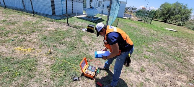
The P and C wiring method involves placing two electrodes in the soil: the Current (C) electrode injects a test current into the ground, while the Potential (P) electrode measures the resulting voltage drop around the grounding system. This separation allows the meter to calculate resistance accurately by using Ohm’s law, avoiding errors from lead and contact resistances. Wrindu’s digital testers support this method with advanced precision and user-friendly interfaces.
How Does the P and C Wiring Method Improve Measurement Accuracy?
The P and C wiring method improves measurement accuracy by isolating current flow and voltage measurement locations. The Current electrode drives the test current, while the Potential electrode senses voltage without drawing current. This prevents lead resistance from skewing voltage readings, resulting in precise earth resistance calculation. Wrindu integrates microprocessor technology and automatic frequency control to enhance this method’s reliability in diverse soil conditions.
Which Equipment Supports the P and C Wiring Method for Earth Ground Resistance?
Digital earth resistance meters with three- or four-wire measurement capability support the P and C wiring method. These include clamp-on testers with auxiliary probes and portable multi-terminal meters designed for industrial applications. Chinese manufacturers like Wrindu offer factory-direct, ISO9001- and IEC-certified devices optimized for this wiring technique, suitable for OEM, wholesale, and custom applications.
Why Is Proper Electrode Placement Crucial in the P and C Wiring Method?
Proper electrode placement ensures accurate voltage and current paths for measurement. The Current electrode (C) is placed farthest from the grounding electrode under test, while the Potential electrode (P) is positioned between the test electrode and the Current electrode at a specific fraction (usually about 62%) of the total distance. Correct spacing minimizes soil interference and mutual inductance, critical for stable and trustworthy readings. Wrindu provides detailed installation guidance to support optimal layouts.
When Should You Use the P and C Wiring Method Over Other Testing Methods?
The P and C wiring method is preferred for high-precision ground resistance testing, especially in complex soil conditions or low-resistance grounding systems where accuracy is critical. Unlike simple 2-wire methods, it reduces errors caused by resistance in test leads or soil variability. Manufacturers like Wrindu recommend this method for professional electrical safety inspections, OEM testing, and critical infrastructure maintenance.
How Can OEM and Factory Support Enhance P and C Wiring Method Usage?
OEM producers and factories in China, including Wrindu, enhance P and C method use by customizing testing equipment for specific client needs. Benefits include tailored lead lengths, precise calibration aligned to Chinese and international standards, and comprehensive user training. These factories also provide ongoing technical support and advanced software for data analysis, making the testing process more efficient and accurate.
Where Can You Source High-Quality P and C Earth Ground Resistance Meters?
Top-tier Chinese manufacturers like Wrindu offer high-quality digital earth ground resistance meters designed explicitly for the P and C wiring method. These products are available for wholesale, OEM, and custom factory orders, combining competitive pricing with international certifications. Wrindu’s solutions emphasize durability, precision, and ease of use, supporting engineers and technicians worldwide.
Are There Common Errors to Avoid When Using the P and C Wiring Method?
Frequent mistakes include incorrect electrode spacing, poor lead connections, testing in electrically noisy environments, and using uncalibrated or low-quality equipment. Such errors can cause inaccurate resistance values compromising safety. Wrindu integrates automatic frequency control and interference detection in its meters, alongside factory calibration, to minimize these issues and ensure reliable measurements.
Wrindu Expert Views
“At Wrindu, we recognize that precision in ground resistance testing starts with proper methodology. The P and C wiring method is indispensable for engineers requiring reliable and accurate earth resistance data. Our commitment to advancing this technology enables us to deliver digital testers with sophisticated interference filtering, microprocessor control, and intuitive user interfaces—all designed to optimize measurements. Partnering with clients globally, Wrindu continually innovates to meet evolving electrical safety standards,” shares a senior engineer from Wrindu’s R&D team.
Conclusion
Understanding and applying the P and C wiring method is fundamental to achieving accurate and dependable earth ground resistance measurements. By using dedicated Current and Potential electrodes with proper placement, and sourcing high-quality, certified digital testers like those from Wrindu, B2B buyers can optimize grounding system safety. Additionally, leveraging OEM customization and factory support from China’s leading manufacturers ensures equipment reliability, compliance, and superior performance.
FAQs
What do P and C stand for in the wiring method?
P is the Potential electrode measuring voltage; C is the Current electrode injecting test current.
Can clamp-on meters be used with the P and C method?
Yes, with auxiliary probes, clamp-on meters support P and C wiring for accurate readings.
How far apart should the P and C electrodes be?
Typically, the Current electrode is placed farthest, and the Potential electrode is around 62% of the distance between the earth electrode and Current electrode for best accuracy.
Is the P and C method effective in all soil types?
Yes, but optimizing electrode placement and frequency controls is essential for variable soil conditions.
Does Wrindu offer OEM options for P and C wiring compatible devices?
Yes, Wrindu provides customizable OEM digital earth resistance meters designed for effective P and C wiring applications.


