
How Should Partial Discharge Testing Methods Be Selected?
Send your test requirement — get a tailored solution and a quote within one working day.
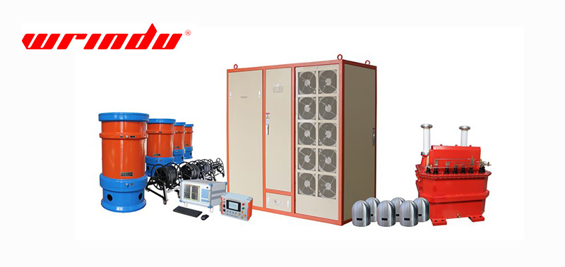
Select partial discharge (PD) testing methods by first defining the asset, the likely defect and the available access point, then choosing the outage position and the evidence level the decision requires. Conventional IEC 60270 measurement provides quantified, comparable values where the test circuit allows; TEV, HFCT, UHF and acoustic methods provide screening, sensitivity and location where conventional coupling is impractical. Match the method family to the asset and the question, not the other way round.
Start with the Asset, Defect and Access Point
Asset construction decides which PD signal is contained and where it can be sensed. A gas-insulated switchgear (GIS) enclosure contains the electromagnetic signal, so UHF sensors coupled at inspection ports are effective. Metal-clad switchgear carries a transient earth voltage on its panels, which is what TEV sensors detect. Cable circuits route the discharge current pulse through terminations and earth straps, which is where HFCT clamps belong. Acoustic energy travels through air and solid structure, which makes ultrasonic sensors useful for location on several asset types.
The defect class influences the method as well. Internal voids and delamination produce measurable discharge activity inside the insulation, surface discharges and tracking produce acoustic and visual signatures, and loose or floating contacts produce signals that can look like discharge. Screening methods identify that activity is present; the discrimination of discharge from noise and the classification of the pattern are separate steps that need their own evidence.
The access point is often the deciding constraint. A compartment with an installed coupler supports UHF; a cable with accessible terminations supports HFCT; an enclosed panel supports TEV. If no access point exists for the preferred method, the plan must use the family that fits the asset, or the asset must be prepared with sensors during the next outage.
| Asset | Typical access and signal | Online method family | Offline / controlled option | Evidence level |
|---|---|---|---|---|
| GIS | UHF couplers at compartments; signal contained by enclosure | UHF survey or continuous monitoring | Offline UHF test at commissioning or after repair | Screening and trend; quantified where conventional coupling is fitted |
| Metal-clad switchgear | TEV on panel enclosure; acoustic from panel surfaces | TEV survey or monitor; ultrasonic scan | Controlled-voltage test with access, where permitted | Relative screening; confirmation by a second family |
| Cable circuits | HFCT at terminations and earth straps | HFCT survey or monitor on critical circuits | Controlled PD test on the isolated cable | Screening and trend; quantified under offline test |
| Power transformers | Acoustic on tank; electrical access limited | Acoustic survey where access exists | Offline PD measurement per the applicable test code | Confirmation and quantification offline |
| Air-insulated bus and open assets | Acoustic and electrical detection at accessible points | Ultrasonic scan during routine rounds | Conventional measurement where the circuit can be arranged | Location and screening; subject to open-air noise |
The matrix is a starting point for selection, not a fixed rule. The final method choice depends on the specific compartment geometry, the sensor access available and the decision the measurement must support.
Conventional IEC 60270 Measurement
IEC 60270 defines conventional PD measurement: the apparent charge of the discharge is quantified in picocoulombs through a defined measuring circuit, with calibration and specified bandwidth. It is the reference method when a quantified, reproducible value is required, and it underpins type, routine and acceptance testing of high-voltage equipment where the test circuit can be arranged.
Conventional measurement requires a coupling circuit, normally a coupling capacitor or detection impedance connected to the test object, which in practice means the equipment is isolated and energised by the test source. That constraint makes it impractical for many installed assets in service, which is where non-conventional methods provide sensitivity and access. The two families are complementary: conventional measurement quantifies, non-conventional methods screen and locate.
TEV, HFCT, UHF and Acoustic Detection Families
Non-conventional electromagnetic and acoustic methods are covered by IEC TS 62478. They do not directly measure apparent charge; they detect a signal that is related to discharge activity, so their results are interpreted as relative indicators supported by trend and multi-sensor evidence.
TEV sensing detects the transient voltage pulse on the earthed enclosure of metal-clad switchgear and is the standard first-line screening method for switchgear panels. HFCT sensors clamp around earth straps or ground conductors and detect the high-frequency current pulses from cable circuits, terminations and joints. UHF sensors detect the electromagnetic waves contained inside shielded volumes such as GIS, where access is available through couplers or dielectric windows. Ultrasonic sensors detect the acoustic pressure waves produced by discharge and by mechanical conditions, and are used both for surface scanning and for pinpointing the source.
Each family answers a different question at a different stage of the investigation: screening finds the suspect asset, a second family confirms that the signal is real and internal, and acoustic or multi-sensor techniques locate the source for inspection. The detailed sensor-by-sensor comparison of physics, assets and limitations is covered by the sensor comparison article, which this framework links to rather than repeats.
Online and Offline Test Boundaries
Online testing measures PD activity under the actual operating stress without an outage, which makes it valuable for screening and for capturing intermittent activity on critical assets. Its results are influenced by load, noise and sensor placement, so they are interpreted as trends and relative indications. Offline testing isolates the asset and applies a controlled test voltage, producing a more repeatable and quantified result that is used for acceptance, commissioning and confirmation after an online indication.
The choice between them is an operational decision about outage cost and evidence standard before it is an instrument decision. A routine screening programme can run online at low cost, while a confirmatory or acceptance measurement usually requires the controlled conditions of an offline test. The full decision logic by asset type is covered in the online versus offline article.
Noise Environment and Sensitivity Requirements
Every PD measurement competes with electrical noise: switching transients, communication signals, corona on nearby conductors and load-related interference. The noise environment of the site decides which method families are usable and how much discrimination work the investigation needs. Sensitivity and noise rejection are a trade-off, and a very sensitive setting can report noise as activity while an insensitive setting misses real discharge.
Build the noise assessment into the method plan. Take background readings at every sensor position, compare the signal with the background and across phases, and use gating or multi-sensor comparison to test whether the signal is local to the asset. The workflow for separating partial discharge from electrical noise is a distinct task with its own evidence rules, covered by the noise-discrimination guide.
Quantification, Pattern Recognition and Location
Different methods produce different classes of evidence, and the report should label each class honestly. Conventional IEC 60270 measurement produces a quantified apparent charge value. Phase-resolved analysis produces patterns that relate activity to the AC cycle and support classification. Survey methods produce relative amplitudes that support trend comparison. Location methods use time-of-flight or acoustic propagation to estimate the source position.
Pattern recognition is an interpretation step, not an automatic verdict: the same phase-resolved shape can be produced by different mechanisms in different assets, and noise can imitate discharge patterns. Location requires synchronised sensors or a structured acoustic pass, and its accuracy depends on the propagation path. State the evidence class, the uncertainty and the confidence level in the record, and combine the methods so that quantification, classification and location reinforce each other.
Building a Multi-Method PD Investigation
A defensible investigation moves through defined stages. Screen the population with the fastest suitable method, for example a TEV or HFCT survey, to identify suspect assets. Confirm the suspect signal with an independent sensor family under stable conditions. Quantify where the asset and access allow, using conventional measurement or a controlled test. Locate the source with acoustic or multi-sensor techniques. Then correlate the finding with other condition data such as dissolved gas analysis and inspection history before the engineering decision.
Document the method selection and its reasoning: the asset, the access points, the outage position, the noise environment, the evidence level required and the result of each stage. The instrument that supports this workflow must cover the sensor families and the recording capability the plan needs; the practical specification of such instruments is covered in the tester selection article. When the investigation identifies a need for new or additional measurement systems, compare the requirements against verified capabilities and request a technical proposal from the equipment supplier.
Frequently Asked Questions
How do I choose between TEV, HFCT, UHF and acoustic sensors?
Choose by the asset and its access point: TEV for metal-clad switchgear panels, HFCT for cable earth paths and terminations, UHF for shielded GIS compartments, and ultrasonic methods for surface scanning and source location. The sensor-to-asset comparison matrix provides the detail behind this choice.
Is online or offline PD testing better?
They answer different questions. Online testing screens and trends under service stress without an outage, while offline testing under controlled voltage provides the repeatable, quantified evidence used for acceptance and confirmation. The right choice depends on the asset’s criticality and the evidence the decision requires.
How can I tell whether a signal is PD or noise?
Use phase relationship, repetition, multi-sensor comparison and background checks, and confirm with a de-energised check where appropriate. A single screenshot is never enough; the discrimination workflow defines the evidence and confidence levels required before escalation.
For instrument selection that supports this method framework, see the partial discharge tester selection guide. Compare the sensor families in the TEV vs UHF vs HFCT vs ultrasonic comparison, review the online vs offline decision and the PD vs noise discrimination guide, and when you need to match a measurement system to your asset list and site conditions, review partial discharge testing solutions and request a technical proposal.
Related articles
 SF6 Leak Detector Sensitivity: Select a Method for the Inspection TaskKnowledge
 Cable Fault Locator Selection for Urban Networks: Routes, Noise and AccessKnowledge
 Substation Battery Load Bank Sizing: Duty, Voltage Range and Heat RejectionKnowledge
 CT Polarity, Ratio and Burden Testing: Find Wiring and Loading ErrorsKnowledge