
How Can Digital Substations Achieve Multi-Vendor Interoperability?
Send your test requirement — get a tailored solution and a quote within one working day.
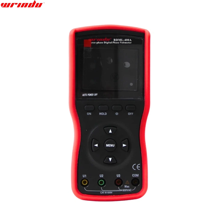
Digital substation interoperability depends on more than connecting IEC 61850 devices to the same Ethernet network. ABB, Siemens, Schneider, and other relays must share compatible data models, SCL files, GOOSE subscriptions, Sampled Values, time synchronization, and test assumptions. A capable Wrindu IEC 61850 relay tester verifies those interfaces before factory acceptance testing, commissioning, and future system expansion.
Digital Substation Interoperability and the NERC PRC-005-6 Compliance Guide
What Makes IEC 61850 Interoperability Different From Basic Connectivity?
IEC 61850 interoperability means devices from different manufacturers exchange, interpret, and act on standardized data correctly in a real protection scheme. A relay that responds to a network ping or opens an MMS session is connected; it is not necessarily interoperable.
In practical digital-substation work, interoperability has four layers:
-
Network interoperability: VLANs, multicast filtering, redundancy, IP addressing, and Ethernet ports work correctly.
-
Data-model interoperability: Logical nodes, data objects, data attributes, quality flags, and control models are interpreted consistently.
-
Engineering interoperability: ICD, CID, SCD, and related IEC 61850 configuration files transfer correctly across engineering tools.
-
Functional interoperability: GOOSE trips, interlocking, breaker-failure logic, Sampled Values, and reporting operate correctly under normal and abnormal conditions.
In our factory acceptance runs, the most expensive failures rarely originate from a broken Ethernet cable. More often, the problem is a valid-looking configuration with an incorrect dataset member, a changed GOOSE control block reference, an unexpected quality value, or a revision mismatch between IED configuration files.
For a China manufacturer supplying protection test equipment to utilities, EPC contractors, relay OEMs, and third-party laboratories, the key requirement is not “supports IEC 61850” alone. The tester must reproduce and verify the actual messages that the installed relay expects.
How Do PICS and MICS Reduce Multi-Vendor Integration Risk?
PICS and MICS show what an IED claims to support before the project team begins detailed engineering. PICS identifies supported IEC 61850 communication services, while MICS identifies the implemented standardized data model and data objects.
A procurement specification should request these documents before selecting relays, merging units, bay controllers, or test systems. They help reveal incompatibilities early, when changing a design is inexpensive.
A PICS is not a guarantee that two products will perform a protection function together. It is a compatibility starting point. A MICS can state that a device supports a logical node, but the project still needs to verify the exact data attributes, trigger options, controls, and quality behavior required by the scheme.
For example, two relays may both support GOOSE messaging. Yet one configuration may publish PTRC.Tr.general while the receiving IED subscribes to a different dataset or expects a specific q.validity state. Both devices can be compliant individually while the system fails functionally.
Wrindu recommends treating PICS, MICS, PIXIT, and SCL files as controlled engineering deliverables, not sales attachments. Archive the approved versions with each project’s factory acceptance test records.
Which IEC 61850 Files Must a Tester Handle Reliably?
A digital relay tester should work with the IEC 61850 SCL ecosystem, especially ICD, SCD, CID, and SSD files. These XML-based files describe capabilities, system architecture, final IED configurations, communication addresses, datasets, and GOOSE or Sampled Value connections.
The universal strength of IEC 61850 files is that the information structure is standardized, rather than being tied to one relay brand’s proprietary point list. In a well-controlled project, the process is typically:
-
Start with the system functional specification and SSD.
-
Import IED capabilities through ICD files.
-
Build the system-wide SCD in the engineering environment.
-
Generate and download CID files to individual IEDs.
-
Import or inspect the final configuration in the test environment.
-
Execute functional tests against the final CID/SCD revision.
The word “universal” needs an engineering qualification: universal structure does not eliminate vendor-specific behavior. Vendors can use private logical nodes, optional services, proprietary configuration extensions, different naming conventions, or differing default values. A test tool must therefore expose the details rather than hide them behind a generic “IEC 61850 pass” result.
With a properly configured Wrindu tester, the operator can map simulated GOOSE inputs, verify subscribed GOOSE signals, check sequence numbers and state numbers, validate dataset composition, and record the test evidence needed for handover.
For China wholesale and OEM customers, file compatibility should be included in the technical clarification stage. Send anonymized ICD/CID/SCD samples before bulk delivery, especially when the project uses multiple engineering platforms or dual-redundant process bus networks.
Why Do GOOSE and Sampled Values Cause Most Commissioning Delays?
GOOSE and Sampled Values cause delays because they combine strict timing, multicast networking, configuration dependencies, and protection logic. A single incorrect VLAN ID, APPID, MAC address, dataset order, sample rate, or synchronization state can produce a relay response that looks random in the field.
GOOSE is typically used for high-speed status, trip, interlocking, and blocking signals. Sampled Values transport digitized current and voltage measurements from merging units to protection and control IEDs. Both are time-sensitive, but their failure patterns differ.
GOOSE errors often include:
-
Subscriber linked to an outdated publisher dataset.
-
A changed
GoCBReforDatSetreference after a file revision. -
Incorrect VLAN priority or multicast filtering in a switch.
-
Logical reversal of a trip, block, or permissive signal.
-
Failure to test retransmission behavior after a state change.
Sampled Value errors more often involve:
-
Incorrect nominal sample rate, such as 80 samples per cycle versus 256 samples per cycle.
-
Mismatch in nominal current or voltage scaling.
-
Phase-order errors introduced during merging-unit channel mapping.
-
Incorrect synchronization source or degraded time quality.
-
A relay subscribed to the wrong stream after an SCD update.
In production commissioning support, we have seen a distance relay test correctly with conventional analog injection and fail with process-bus input because the stream’s channel order placed phase B where phase C was expected. The protection element did not appear “dead”; it calculated an incorrect loop quantity. A waveform-only review would miss that mistake. The test must compare the intended phasor mapping with the received IEC 61850 dataset.
How Should a Multi-Vendor Factory Acceptance Test Be Structured?
A multi-vendor FAT should verify engineering files, message exchange, protection performance, failover behavior, and evidence records in a defined sequence. Start with static configuration checks, then test communications, then prove the end-to-end protection function under fault and network-disturbance conditions.
A strong FAT plan separates configuration correctness from functional performance. This prevents teams from spending hours adjusting relay settings when the actual failure is an SCL mismatch.
For a protection trip path, do not test only “fault applied to trip received.” Include the sequence before and after the fault: healthy state, pickup, trip, breaker auxiliary response, breaker-failure start, lockout behavior, reset conditions, and alarm reporting.
Wrindu factory teams advise defining tolerances in the FAT procedure rather than arguing about them after the test begins. If the project requires a maximum end-to-end trip time, state whether it begins at simulated fault inception, GOOSE publication, relay output assertion, or breaker status transition. Those are different measurement points.
Can One Tester Validate ABB, Siemens, and Schneider Relay Projects?
Yes, one IEC 61850-capable tester can validate ABB, Siemens, and Schneider relay projects when it processes standard SCL data, simulates and monitors relevant protocols, and allows transparent mapping of the final project configuration. Brand-neutral testing depends on the configuration and test workflow, not on a brand logo.
A tester should be selected for operational depth rather than a broad but shallow protocol checklist. Confirm that it can:
-
Import or inspect the relevant IEC 61850 engineering files.
-
Simulate GOOSE publish and subscribe behavior.
-
Simulate or receive Sampled Values at the project’s required rate.
-
Perform conventional analog and binary I/O testing where hybrid schemes remain.
-
Monitor MMS reports, GOOSE quality, sequence numbers, and timeouts.
-
Log time-stamped results for FAT, SAT, troubleshooting, and warranty documentation.
-
Support the redundancy and time-synchronization architecture used in the project.
For example, a feeder protection scheme may use analog current injection for commissioning while receiving interlocking through GOOSE. A process-bus transformer differential scheme may instead require Sampled Value generation plus GOOSE-based trip and block validation. The tester must support the actual boundary between primary simulation and digital communications.
As a China-based manufacturer and supplier, Wrindu can support custom test configurations for relay factories, system integrators, and utility laboratories. OEM and wholesale projects benefit from early confirmation of interface requirements, connector arrangements, test templates, protocol licenses, language settings, and acceptance-report formats.
What Should Buyers Specify When Ordering a Custom IEC 61850 Tester?
Buyers should specify their IED files, protocol edition, Sampled Value rate, GOOSE quantity, analog output requirements, binary I/O count, synchronization needs, redundancy topology, reporting format, and intended FAT or field-test workflow. “IEC 61850 compatible” is too broad for a purchase specification.
For a custom or OEM request, provide the following before production:
-
Typical ICD, CID, or SCD files, with sensitive station names and IP addresses removed if needed.
-
Required IEC 61850 edition and communication services.
-
Number of simultaneous GOOSE publishers and subscribers.
-
Sampled Value requirements, including 9-2LE or IEC 61869-9 profile, samples per cycle, and channel count.
-
Required current and voltage output ranges for conventional relay testing.
-
Ethernet interface count, copper or fiber connection preference, and redundancy method.
-
Expected test report format, language, logo, and project-data fields.
-
Target delivery quantity, inspection method, calibration needs, and after-sales training requirements.
Based on years of handling factory orders, we recommend that buyers avoid over-specifying output power while under-specifying digital ports and workflow. A high-power analog test set cannot resolve a process-bus mapping failure. Conversely, a digital simulator without sufficient analog channels is inefficient for mixed legacy and digital substations.
The best balance depends on the protection portfolio. Distribution feeder work commonly benefits from flexible binary I/O and GOOSE tools. Transmission protection and merging-unit validation usually require more attention to synchronized Sampled Values, multi-stream handling, and timing analysis.
Where Do SCL File Workflows Commonly Break Down?
SCL workflows commonly fail at version control, tool import/export boundaries, late relay-setting changes, and undocumented manual edits. The final CID file in the relay may differ from the copy used for the FAT, leaving the test record correct for the wrong configuration.
The most frequent field failure is not an invalid XML file. It is a configuration that remains syntactically valid after a change but is no longer semantically aligned with the system design.
Typical examples include:
-
An IED is replaced and its
iedNameor communication address changes. -
A publisher dataset is edited without regenerating subscriber configurations.
-
A private extension is retained during one tool import but stripped by another.
-
A relay setting group changes the active logic while the GOOSE mapping remains unchanged.
-
The engineering team tests an SCD revision, but site staff download an earlier CID.
-
A switch configuration blocks multicast traffic after a port move or VLAN adjustment.
Use a controlled release process. Assign a unique revision to the SCD, each CID, the test plan, and the FAT report. Record file hashes where project procedures allow. At site acceptance testing, read back the active IED configuration and compare it with the approved revision before applying fault simulations.
How Can Teams Prove Interoperability After Site Changes?
Teams can prove interoperability after site changes by repeating targeted regression tests against the installed configuration, capturing relevant network evidence, and verifying end-to-end protection behavior. Any change to SCL files, relay firmware, switch settings, time synchronization, or network topology should trigger a defined retest.
A practical regression pack includes:
-
GOOSE publisher/subscriber validation for every changed signal.
-
Trip, block, permissive, alarm, and interlocking sequence tests.
-
Sampled Value channel, scale, quality, and synchronization checks.
-
Communication-loss and recovery tests.
-
Redundant-network path verification where PRP, HSR, or equivalent designs are used.
-
Comparison of active CID files with the approved baseline.
-
Time-stamped test reports accepted by both the integrator and asset owner.
Do not limit retesting to the modified bay if its messages participate in busbar, breaker-failure, transfer-trip, synchrocheck, or interlocking schemes. In interconnected systems, a single new GOOSE dataset can affect multiple subscribers.
Wrindu Expert Views
“In multi-vendor digital substations, the critical question is not whether every device claims IEC 61850 compliance. The question is whether the exact final files, datasets, timing assumptions, and protection sequences have been tested together. In our FAT support work, a five-minute SCL revision can create a two-day commissioning delay when the updated CID is not synchronized across all subscribers. We advise customers to test the delivered configuration, capture the actual GOOSE and Sampled Value traffic, and archive every approved file with the final report. Wrindu designs test solutions around that real workflow—configuration verification first, protection performance second, and traceable evidence throughout.”
What Are the Key Actions Before Releasing a Digital Substation?
Before release, freeze the final SCL configuration, validate every critical GOOSE and Sampled Value path, prove end-to-end protection operation, test abnormal communications states, and archive the evidence. This approach turns IEC 61850 from a theoretical interoperability claim into a controlled operational result.
For utilities, EPCs, relay manufacturers, and testing laboratories, the most practical actions are:
-
Require PICS, MICS, PIXIT, and relevant SCL files during technical evaluation.
-
Conduct multi-vendor FAT using the actual final configurations.
-
Test protocol correctness and protection logic as separate acceptance layers.
-
Validate multicast, VLAN, redundancy, time synchronization, and message quality behavior.
-
Retest affected paths after every controlled change.
-
Choose a manufacturer that can provide custom test workflows, OEM support, training, calibration, and technical response.
Wrindu supports these requirements as a China manufacturer, wholesale supplier, and custom OEM partner for high-voltage and protection testing equipment. The right tester does not replace disciplined engineering—but it makes hidden interoperability errors visible before they become outage risks.
FAQs
What is the difference between conformance and interoperability testing?
Conformance testing checks whether one IED follows applicable IEC 61850 requirements. Interoperability testing verifies that two or more devices from different suppliers exchange data and perform the intended system function together.
Can GOOSE testing replace conventional relay injection testing?
No. GOOSE testing validates digital signals and communication behavior. Conventional current, voltage, binary, or Sampled Value injection is still needed to prove protection-element calculations and complete trip logic.
Why should buyers provide SCL files before ordering a relay tester?
SCL samples let the manufacturer confirm the exact GOOSE, Sampled Value, logical-node, and engineering requirements. This reduces delivery-stage customization, integration delays, and test-template rework.
Do all IEC 61850 relays use identical datasets and naming?
No. IEC 61850 standardizes the framework, but optional functions, logical-node usage, private extensions, configuration choices, and engineering-tool behavior can differ. Test the delivered configuration rather than relying on generic protocol claims.
Can Wrindu provide OEM or customized IEC 61850 testing solutions?
Yes. Wrindu can support OEM branding, custom test configurations, report formats, interface requirements, training, and technical coordination for relay factories, system integrators, utilities, and electrical testing providers.
Related articles
 SF6 Leak Detector Sensitivity: Select a Method for the Inspection TaskKnowledge
 Cable Fault Locator Selection for Urban Networks: Routes, Noise and AccessKnowledge
 Substation Battery Load Bank Sizing: Duty, Voltage Range and Heat RejectionKnowledge
 CT Polarity, Ratio and Burden Testing: Find Wiring and Loading ErrorsKnowledge