Cable fault testing
RuiDu Mechanical: Your Reliable Cable Fault Locator Supplier!
RuiDu Mechanical and Electrical (Shanghai) Co., Ltd. is a leading global power testing equipment manufacturer and system solution provider. Our company was established in 2014. Our main products are substation transformers, high-voltage switches, transformers, lightning arresters, batteries, cable faults, relay protection, insulation withstand voltage, transformer oil injection equipment, etc. Our factory covering an area of more than 50,000 square meters, 6 product production lines and more than 200 employees, selling the products to more than 120 countries and regions. In addition, we support high-volume production, calibrate and test instruments at the point of sale, providing repair instructions for these products.
Rich Experienced
Our team has more than 10 years of experience in the industry, providing customers with compliant, high-quality equipment, and developing friendly cooperation with partners such as Kenya Power, UETCL, TCN, EVN, PLN, NGCP, CFE.
Wide Product Range
Our broad product offering includes digital multimeters, power analyzers, thermal imaging cameras, insulation resistance testers, accessories and integrated test tools. These test devices can be easily integrated into a variety of electrical and electromechanical systems.
Guaranteed Quality
Our production workshops are professionally assessed, developed and validated, equipped with a range of analytical instruments and all products have international ISO 9000 series, IEC and CE certifications.
Customized Service
According to your usage needs, our team is online 24/7 to provide you with detailed consultation and after-sales service, and provide OEM and ODM customized products.


What is Cable Fault Locator?
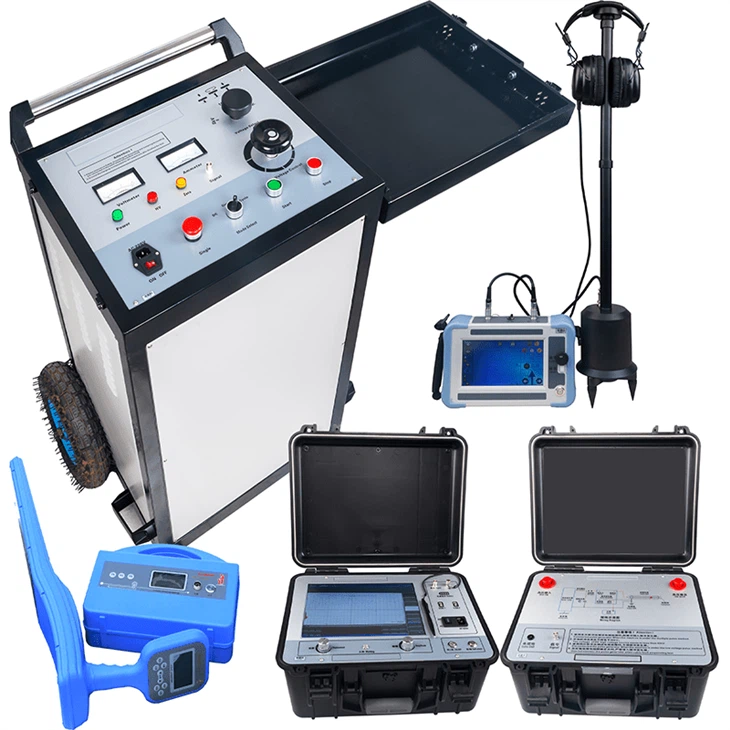
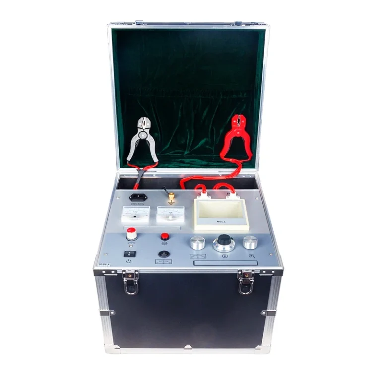
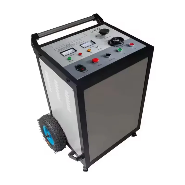
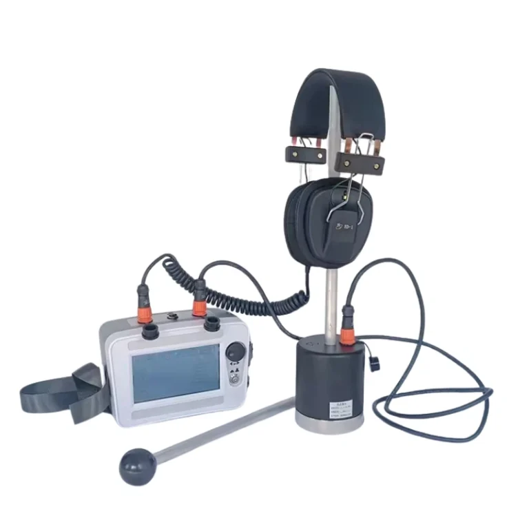
A cable fault locator is a device that can identify faults or disruptions in a cable. It works by sending a signal through the cable and measuring the signal that is returned. This allows the device to identify faults such as breaks, cuts, or other damage. For example, the surge and test generator is designed for testing of cables and cable sheaths and for the precise location of high-resistance and intermittent faults. The process of locating periodic faults, such as insulation faults in cables, is called cable fault location. The fault location procedure is carried out in four steps: Fault analysis, Pre-location, Tracing and pin-pointing, Cable identification.
Features of Cable Fault Locator
Friendly User
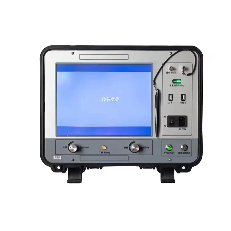
Our cable fault locators feature a large high-definition display that shows fault type (open or short), battery voltage, propagation speed setting, charging voltage, and can be connected to a computer to retrieve and view fault wizard software.
Easy to Use
Their system, based on the new Automated Arc Reflection Technology (AART) developed by IUP, features a loop mode that pinpoints faults via headphone listening devices and automatically reads the distance to the fault location.
Energy Saving
When in standby mode for more than ten minutes, these locators will automatically turn off the screen display to save power, and when the battery is low, the battery voltage will flash on the display to remind you to charge.
Durable Construction
Their internal systems are environmentally protected and housed in an extremely durable rotationally molded polyethylene housing and are IP65 water and dust resistant to allow testing in any extreme environment.
Types of Cable Fault Locator
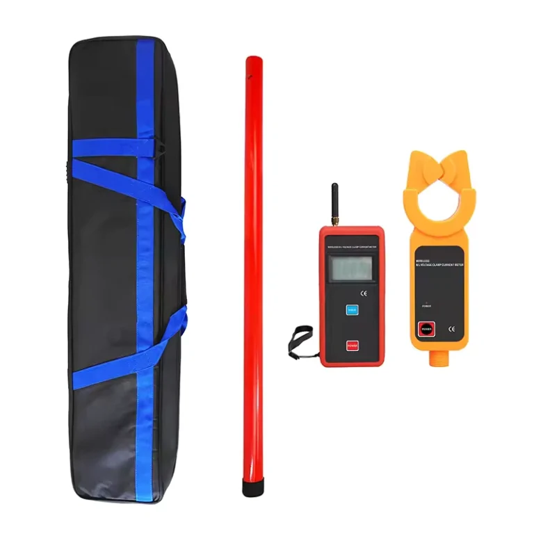
Cable Route Tracer
A cable route tracer is a device that can locate, trace, and measure the depth of buried power cables. It can also identify the path of underground cables and help with maintenance efforts like fault localization and rectification.
Cable tracer typically consists of two parts: a transmitter that sends a search signal onto the cable, and a receiver that picks up the signal and allows the locator operator to trace the signal’s path. Many tracers can detect 60 Hz or 50 Hz frequencies. Higher frequencies can pick up more signals, while lower frequencies can help follow a particular line.
A cable route tracer can also pinpoint low resistance faults by connecting a powerful audio frequency generator across the faulty cores of the CUT. The signal travels up to the fault, emitting a low signal that is detected by the route tracer sensor coil and displayed on an audio receiver.
Cable Fault Distance Locator
A cable fault distance locator detects the exact location of an underground cable fault and its distance from the base station. It uses a micro controller and a set of resistors to represent the cable. A dc voltage is fed at one end, and an analog to voltage converter detects the change in voltage. A microcontroller then calculates the necessary calculations to display the fault distance on an LCD display.
The project work is intended to detect the location of fault in underground cable lines from the base station in km using a micro controller. To detect a fault in the cable, thecable must be tested for faults. This prototype uses the simple concept of Ohms law.
Cable fault location can also be done by evaluating the time difference between the acoustic signal and the electromagnetic impulse of the shock discharge. When the shortest time difference is indicated, the exact fault location is revealed.

Common Reasons of Cable Faults
Screening Faults
A contact between conductor and screen generates a varying resistance.
Phase Faults
The contact between multiple conductors generates a varying resistance.
Sheath Faults
Sheath faults are damage of the cable sheath that allows the surroundings contact with the cable screen.
Faults Due to Moisture
Water penetrates into the cable sheath and contacts the conductors. Impedance changes at the fault location make measuring more difficult. The resistance usually lies in the high-ohmic range.
Disruptions
Combination of series and parallel resistances, usually in the form of a wire break. The voltage is interrupted, i.e. Ω=∞ .
Methods to Locate the Cable Faults
Pre-location
Time Domain Reflectometry (TDR)
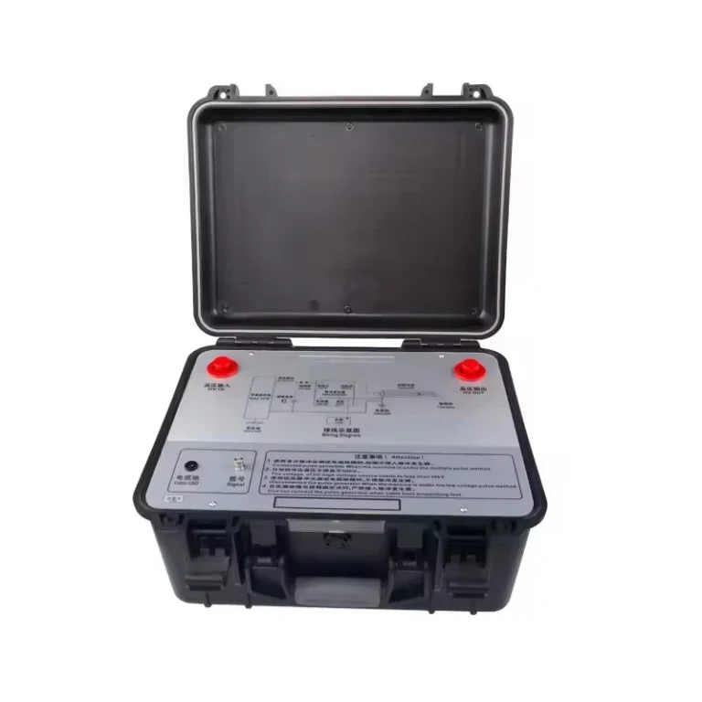
The TDR method is the most established and widely used measuring method for establishing the total length of a cable and the distance of low resistive faults, cable interruptions, and the location of joints along a cable. When a low voltage pulse is sent into a cable that has a parallel path of two conductors, reflections will be seen at points along the cable that exhibit different impedances.
Secondary Impulse Method / Multiple Impulse Method (SIM/MIM)
SIM/MIM is also known as surge arc reflection and is based upon a surge generator or thumper being coupled together with a TDR. A high voltage impulse is sent down the cable causing the fault to break down and temporarily transforms a high resistive fault into a low resistive fault, which can be detected by a TDR signal to measure the fault distance. Fault distance evaluation is conducted fully automatically.
Impulse Current Method (ICM)
ICM is the conventional location method for high resistive cable faults in very long cables. A surge generator/thumper is coupled to a TDR via an inductive coupler. The breakdown in the fault generates a current impulse, which travels along the cable sheath between the surge generator/thumper and the cable fault causing reflections that are detected by the TDR.
Cable Sheath Fault Location (Bridge Measurement)
When a fault occurs between two defined cores or parallel wires the theory of time domain reflectometry (TDR) can be applied, as is the case for all the pre-location methods described above. However, certain cable structures can allow faults to happen from a core to the outside ground or soil, such as in unshielded cables or when there is damage to the outer sheath of a cable. Cable sheath faults will not immediately cause cable failures, but over time the performance of the cable can be compromised because water can penetrate into the cable causing corrosion and the growth of possible water trees. For these types of faults measuring bridge techniques must be employed.
Decay Method
In certain cables the breakdown voltage of the fault may be higher than the rated output of the surge generato. In this case a VLF or DC source with higher voltage output needs to be used as the high voltage source. The decay method is based on voltage decoupling by a capacitive voltage divider. The faulted cable is charged by applying high voltage VLF or DC up to the breakdown voltage. Compared to the ICM method above, the decay method is based on a transient voltage wave that is continuously recorded by the capacitive coupler.
Differential Impulse Current Method / Differential Decay Method
The differential ICM or decay methods can be used for cable faults that are very difficult to locate, such as in very long cables, in a T-branch network, or in overhead transmission lines. For this method, two cables are required for the pre-location process – the faulted cable and a healthy auxiliary cable.
In a first step, the HV impulse is released into the healthy cable and faulted cable simultaneously, giving a first differential picture. Second, a linking bride is connected at the far end of the two cables.
Pin-point Fault Location
Cable Tracing
A successful cable fault location relies on knowing the position of the cable and other lines laid in the soil. If the exact route of the underground cable is not known magnetic frequency procedures can be used to establish the position and depth of the cable using the minimum or maximum method. An audio frequency generator can be connected to a healthy phase of the faulted cable via galvanic connection, inductive connection with a clip-on CT clamp, or inductive connection with a frame antenna. Galvanic connection is considered the best method because the best signal values can be obtained.
Acoustic Fault Pin-Pointing
The acoustic fault location method is used for pin-pointing of high resistive or intermittent faults in buried cables in which the cable is “thumped”, i.e., a series of high voltage surge pulses are sent down the cable causing the fault is break down. During a flashover an audible acoustic signal is generated that can be detected on the ground surface by using a ground microphone, receiver, and headphone. The closer the distance to the fault, the higher the amplitude of the flashover sound.
Step Voltage Fault Pin-Pointing
Cable sheath faults or short circuit faults to ground do not allow for a flashover when thumping a cable, and therefore, acoustic fault pin-pointing cannot be applied. In this case, a sequence of voltage impulses (step voltages) is sent into the faulted cable, which produces a voltage drop to ground. The voltage drop results in a voltage gradient, which can be measured with the use of two earth probes above ground. When walking towards the fault, an increasing voltage should be detected and immediately over the fault a detectable polarity change will be measured and the resulting voltage will be zero when the earth probes are placed symmetrically above the fault.
Twist Field Location
Despite reverse current directions, a magnetic field is produced and using a detecting rod the maximum and minimum of the signal can be detected due to the twist or steady change of geometrical position of the cores in the cable. Since the audio signal returns at the fault position, the position at which no signal can be detected can be determined as the cable fault. The twist field method can also be used to detect cable joints, as the twisted field is interrupted according to the length of the joint.
Cable Identification
If a violent cable fault has occurred and is visible, then it is fairly easy to distinguish which cable needs to be repaired. However, in other circumstances, especially when multiple cables are bundled together, the correct cable has to be identified first to reduce the chances of cutting a section of healthy cable that does not require any repair.
Cable identification is conducted by connecting a transmitter onto the suspected faulted cable, either galvanically or inductively. The transmitter contains a capacitor that is charged and then discharged into the cable. A flexible coupler (Rogowski coil) is then used to measure the current pulse in the target cable.
Factors to Consider When Choose Cable Fault Locator
Requirements and Budget
Before choosing a cable fault tester, you first need to clarify your needs and budget. The functionality and performance of the required tester need to be determined based on factors such as actual work scenarios, cable types, and fault frequencies. At the same time, budget is also an important consideration factor, which requires weighing the prices of different brands and models of testers based on actual situations.
Brands and Manufacturers
When choosing a cable fault tester, it is recommended to choose a well-known brand and manufacturer. These manufacturers usually have a high level of technical expertise and comprehensive after-sales service, and can provide testing equipment with reliable quality and stable performance. In addition, products from well-known brands and manufacturers usually have a high market share and good reputation, which can provide better protection for use and maintenance.
Parameters and Performance of the Tester
When selecting a cable fault tester, it is necessary to pay attention to its parameters and performance, including test signal type, test accuracy, test distance, display mode, etc. Here are some key parameters and performance:
●Test signal type
Different brands of testers may use different signal types for testing, such as high-frequency pulse signals, audio signals, etc. It is necessary to select the appropriate signal type for testing based on the cable type and fault type.
●Test accuracy
Testing accuracy is an important indicator for measuring the accuracy of a testing instrument, including distance accuracy, resistance accuracy, etc. It is necessary to select high-precision testers based on actual needs to improve the accuracy of fault localization.
●Test distance
The testing distance refers to the maximum distance that the tester can detect and locate cable faults. The required testing distance needs to be determined based on factors such as the length of the cable and the location of the fault point.
●Display method
The display methods of the tester include screen display, printout, etc. It is necessary to choose an appropriate display method based on actual needs to facilitate observation and recording of test results.
Usability and Reliability of the Tester
In addition to parameters and performance, usability and reliability are also factors that need to be considered when selecting a cable fault tester. Here are some key considerations:
●Usability
The operation of the tester should be simple and easy to understand, and the interface design should be user-friendly to facilitate users to quickly grasp the usage methods. In addition, the tester should have some automated functions, such as automatically identifying cable types, automatically calculating distances, etc., to improve usage efficiency.
●Reliability
The tester should have high stability and durability, and be able to operate normally in different environments and conditions. In addition, the tester should have some protective measures, such as overload protection, short circuit protection, etc., to protect the safety of the equipment and personal safety.
Scalability and Upgradability of the Tester
When selecting a cable fault tester, it is also necessary to consider its scalability and upgradability. Here are some key considerations:
●Scalability
The tester should have a certain degree of scalability and can be easily connected and used in conjunction with other devices. For example, it can perform data sharing or remote control functions with other electrical measuring instruments, computers, and other devices.
●Upgradability
With the continuous development of technology and changes in application requirements, the functionality and performance of the tester may need to be upgraded and updated. Therefore, it is recommended to choose a tester with an upgrade interface or programmable controller for future functional expansion and upgrades.
Certificate Photo

Factory Photo
FAQ
Q: How does a cable fault locator works?
A: A cable fault locator works by sending a signal through a cable and then measuring the signal that is returned. This allows the device to identify any faults or disruptions in the cable, such as breaks, cuts, or other damage.
Q: What is meant by cable fault?
A: A cable fault is when the insulation of a power cable deteriorates enough that it’s no longer able to contain the voltage, causing a short.
Q: How do you detect cable faults?
A: A Time Domain Reflectometer (TDR) sends a short-duration low energy signal (of about 50 V) at a high repetition rate into the cable. This signal reflects back from the point of change in impedance in the cable (such as a fault). TDR works on the similar principle as that of a RADAR.
Q: What are the three common cable faults?
Common types of cable faults:
(1)Short-circuit.
(2)Short-circuit to earth.
(3)Cable sheath faults.
(4)Intermittent faults.
(5)Cable breaks.
Q: What are the different types of cable locators?
Here are some commonly used types and their specific applications:
(1)Electromagnetic Locators: These are the most commonly used and are ideal for locating metallic cables and pipes.
(2)Acoustic Locators: These are best suited for locating plastic pipes that are filled with water.
(3)More items.
Q: How do you trace an underground cable fault?
A: As a result, a thumping sound can be heard on the surface of the ground. To locate the defect in the underground cable, a repair crew has to walk along the surface of the ground listening for this thumping sound. Once the fault is pinpointed, the crew digs a hole and repairs the faulted cable.
Q: How does Megger find cable fault?
A: This device evaluates the time difference between the acoustic signal (speed of sound) and the electromagnetic (nearly the speed of light) impulse of the shock discharge. When the shortest time difference is indicated, the exact fault location is revealed.
Q: How do you find a bad wire underground?
A: There are many different kinds of wire detectors, but they do the same thing. NF-826 Underground Wire Locator is able to detect the electric wire’s signal below the ground.
Q: What is the most common cause of cable failure?
A: Electrical Overloading. In domestic applications this is often a result of plugging too many appliances into the one socket and overloading the wiring to that individual socket, extension adaptor or gang socket.
Q: How long does it take to fix a cable fault?
A: Over 33% of all cable faults are due to subterranean causes, such as earth movement or external damage. On average, it takes 24 hours to detect and repair a subterranean cable fault, resulting in substantial downtime for businesses.
Q: What are the common faults in underground cables?
A: The following are the faults most likely to occur in underground cables: Open-circuit fault: When there is a break in the conductor of a cable, it is called open circuit fault. The open-circuit fault can be checked by a megger.
Q: What are the colors of cable locator?
A: Red – electric power lines, cables, conduit, and lighting cables. Yellow – natural gas, oil, steam, petroleum, or gaseous materials. Orange – communications, alarm/signal lines, cables, or conduit. Blue – potable water lines.
Q: What is the most common coaxial cable fault?
A: Other than “physical” Cable damage, frequent failure is caused by moisture in open environment, from rain or condensation. Moisture wicks into Cable causing loss and destroys signal fidelity. Yet Most common Failure of coax is failed connector. Usually the result of an error in connector installation.
Q: Which wire only carries a current when there is a fault?
A: The earth wire. The earth wire (Green and Yellow) – this is a safety wire which is used for safety. This wire only carries a current if a fault occurs and prevents the appliance from having electricity running through it and thus preventing the appliance from becoming live.
Q: What causes coaxial cable to go bad?
A: Many things can affect the performance of your coax wiring and a weakened or lost Internet signal: outer protective sheath becomes chewed, cut or damaged. inner wires become bent or broken. multiple splitters are used throughout the home.
Q: Why does my cable keep going out?
A: Cable outages can happen for many reasons. ISP failures, hacking, faulty hardware, failing software, user error, poor network equipment, and local disruptions to service are all culprits that can prevent the end-user from accessing their cable connection. Not all cable outages can be addressed by the consumer.
Q: How do I find an underground electrical short?
A: Cheapest and easiest: Put a load (e.g., incandescent light bulb) on the short circuit (A to neutral). Then follow the cable with a non-contact AC current detector. The detector will stop beeping where the (first) short circuit is, since that is where the current is able to loop back in the cable.
Q: How does a ground fault locator work?
A: The ground fault detector works by injecting an AC signal into the bus system with respect to ground using the signal generator. The signal path is then traced using current clamps connected to the signal receiver.
Q: Will a metal detector find buried electrical wire?
A: Short answer, yes they do! Most metal detectors can identify underground cables as long as they are buried within your machine’s range. A detector’s signal will easily penetrate the plastic pipe and detect the metallic wire inside the power line.
Q: What are the disadvantages of underground cable fault detector?
A: The main disadvantage is that the underground cables have higher initial cost and insulation problems at high voltages. Another main drawback is that, if a fault does occur, it is difficult to locate and repair the fault because the fault is invisible.