
Substation Commissioning Test Sequence: What Happens Before Energisation
Send your test requirement — get a tailored solution and a quote within one working day.
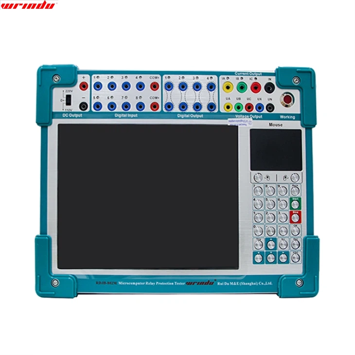
Most commissioning programmes contain the right tests and perform them in an order that makes the results hard to use. A substation commissioning test sequence matters because each test establishes the precondition for the next, and a finding that appears out of sequence cannot be attributed to anything. The sequence is not administrative; it is what makes a finding actionable.
The sequence runs from the physical installation, through the individual equipment, to the systems, and finally to the checks that precede energisation. Each stage produces evidence that the next stage assumes.
Why sequence matters more than any single test
A protection scheme test cannot be attributed if the current transformer circuits have not been proved. A trip test cannot be attributed if the DC supply has not been established. A transformer energisation check cannot be attributed if the pre-energisation tests were recorded without the fingerprint that makes them comparable.
Running the tests out of order produces the same results on a sound installation, which is why the problem is often invisible until an installation with a defect is commissioned. At that point the finding cannot be traced, and the resolution is usually to repeat large parts of the programme.
The sequence also determines how much of the work can run in parallel. Tests that share a precondition and a connection set can be grouped; tests that depend on each other cannot, and attempting to parallelise them produces results that are individually valid and collectively unattributable.
Asset-by-asset sequence before energisation
| Stage | What it establishes | What it depends on |
|---|---|---|
| Installation verification | The equipment is installed as the drawings show and is mechanically complete | Civil and erection work complete; as-built drawings available |
| Wiring and continuity checks | Secondary, control and DC distribution circuits are continuous and correctly terminated | Installation verification |
| Instrument transformer tests | Ratio, polarity, burden and insulation of current and voltage transformers | Wiring checks complete |
| Individual relay and device tests | Each device operates according to its settings and configuration | Instrument transformers proved; as-installed settings recorded |
| Transformer and switchgear tests | Ratio, resistance, insulation, loss, timing and contact condition | Installation complete and equipment isolated |
| DC system verification | Battery capacity, charger performance and trip supply voltage under load | DC distribution installed and connected |
| Scheme and functional tests | Protection and control schemes operate as designed, including interlocks and trip circuits | Individual devices and DC system proved |
| Pre-energisation checks | The installation is ready to be energised and the baseline records exist | All previous stages complete and their evidence accepted |
The order of the instrument transformer and individual device tests is the one most often reversed under schedule pressure, and it is the reversal that produces the largest number of unattributable findings.
Prerequisites: civil, erection and access
Testing that starts before the installation is stable produces results that have to be repeated. A cable termination completed after the instrument transformer test, or a panel re-wired after the relay test, invalidates the earlier evidence.
The prerequisites should be stated as completion criteria rather than as activities: the civil work in the area complete, the equipment erected and aligned, the access arrangements in place, and the as-built drawings available in the revision that matches the installation.
Access deserves specific attention because it constrains the sequence across contractors. Where one contractor’s work requires an area another is still occupying, the test sequence has to accommodate that, and the plan should identify those constraints rather than discovering them on site.
Interlocks, protection and control checks
Interlocks and control functions are tested as functions, not as devices. Proving an interlock means creating the blocking condition and confirming that the prevented operation does not occur, which is a different test from confirming that the interlock is enabled.
Protection and control scheme tests belong after the individual devices have been proved, because a scheme failure is far easier to attribute when the devices are known. The scheme test then exercises the relationships: which device trips which breaker, what blocks what, and what happens when a measurement circuit fails.
The trip supply deserves a specific check at this stage. Testing a trip circuit at the voltage the battery will actually provide during a fault condition, rather than at nominal voltage, is what reveals voltage drop in the wiring and confirms the coordination between the DC system and the protection. The measuring relay requirements that the devices are verified against are defined in IEC 60255-1.
Documentation gates between stages
A documentation gate is a point at which the previous stage’s evidence must exist and be accepted before the next stage begins. Gates prevent the situation where a later finding cannot be attributed because the earlier evidence was never recorded.
The gate should specify what evidence is required: the results, the conditions, the instrument identification and the configuration as installed. A gate that requires a result without conditions is a gate that accepts an unusable record.
Gates also make the sequence visible to the people performing the work. A team that knows the next stage cannot start until its evidence is accepted records the evidence rather than reconciling it later.
Coordination across contractors
Substation commissioning involves several organisations whose work interleaves: civil, erection, cable installation, protection and control, and the testing organisation itself. The sequence has to be agreed across them rather than within each.
The practical arrangement is a single commissioning schedule with each activity’s prerequisites and completion evidence stated, owned by one coordinator. Where each contractor sequences its own work, the interfaces between them are where the sequence breaks down.
The coordination requirement extends to the equipment. Test sets and instruments are shared between activities, and the schedule should show where the same equipment is required by two activities at once. That conflict is easier to resolve in planning than in the week it occurs.
Compressing the window without skipping evidence
Compression comes from three places: grouping tests that share a connection set, running independent activities in parallel, and completing preparation before the window opens.
Grouping is the largest opportunity. Tests that require the same isolation, the same connections and the same instrument can be performed in one pass, and the sequence should be built around those groupings rather than around the test categories in a standard.
What cannot be compressed is the dependency itself. A relay test performed before the current transformer is proved produces a result that has to be repeated, which costs more time than the sequence would have. The schedule should identify the critical dependency chain and compress everything else around it.
Sign-off to energise
The sign-off to energise is the point at which the evidence for every previous stage is complete and accepted. It should be a specific document with named signatories, and it should state what has been verified and what has not.
The statement of what has not been verified is the part most often omitted and the part that matters most at the first energisation. Where a test was deferred, or performed to a reduced extent, the sign-off should record it so that the energisation decision is made knowingly.
The sign-off should also identify the hold points: the stages of energisation at which a check is performed and a decision taken before proceeding further. The first energisation of a transformer, the first operation of a breaker and the first trip test are all natural hold points.
Pre-commissioning checks that prevent re-testing
Several checks performed before the main tests prevent the need to repeat them. Confirming that the equipment is installed as the drawings show, that the connections match the configuration the test assumes, and that the ground connections are in place all prevent the commonest causes of a repeat.
Recording the fingerprint measurements before the equipment is energised is the second group. A frequency response trace taken at commissioning becomes the baseline for every future comparison, and one taken after an event is worth less because the pre-event condition is unknown.
The third group is the state of the equipment itself: cleanliness, moisture and the condition of the insulation surfaces. Those affect the measurements that follow, and dealing with them first avoids attributing their effect to the equipment. The installation requirements that the commissioning programme demonstrates are set out in IEC 61936-1, the transformer evidence required is defined in IEC 60076-1, the switchgear requirements are in IEC 62271-1, and independent acceptance practice is published by NETA.

Energisation stages and their hold points
Energisation is staged: the incoming supply, the busbars, the transformers and the outgoing circuits in sequence, with checks at each stage before the next proceeds. The staging limits the exposure if something is wrong and makes a finding attributable to the stage at which it appears.
Each hold point should define what is checked and what the criterion is. A voltage check, a phase rotation check and a protection in-service check are typical, and each should have a stated expected result rather than an observation.
The hold points should also define who authorises the progression. An energisation that proceeds without the authorisation of the previous hold point is how a finding that was visible at one stage becomes a failure at the next.
When a stage fails: containment and recovery
A failed stage is stopped, and the failure is contained so that it does not affect equipment already tested. On an electrical installation the containment may involve isolation, and on a protection scheme it may involve disabling a function that is operating incorrectly.
The cause should be established before any repeat. Repeating a failed test without establishing the cause is how an intermittent defect is recorded as a pass, and it is the mechanism by which a commissioning programme produces a clean file and an unreliable installation.
The recovery should be recorded with the failure, the cause, the corrective action and the repeat result. That record is what allows the handover package to show the state of the installation honestly, including the events that occurred during its commissioning. Project records of comparable supply and commissioning work are listed under typical achievements, the equipment the sequence uses is listed under all electrical testing equipment, and support arrangements for a commissioning programme are described under testing services and OEM/ODM solutions.
A test sequence is the document that makes a finding attributable, which is what a schedule alone does not do.
Send your commissioning scope and the contractor interfaces to our engineering team and we will help you order the stages and place the documentation gates. The instruments each stage uses are listed under all electrical testing equipment.
FAQ
Why does sequence matter more than the tests themselves?
Because each test establishes the precondition for the next. A protection scheme cannot be verified before its current transformers have been proved, and a scheme test cannot be attributed before the individual devices have been tested. Running the tests in the wrong order produces the same results on a good installation and an unresolvable set of findings on one with a defect.
What are the prerequisites before testing begins?
Civil and erection work complete for the area concerned, access and safe working arrangements established, the as-built drawings available, and the equipment confirmed installed according to them. Testing that starts before the installation is stable produces results that are repeated when the installation changes underneath them.
What is a documentation gate?
A point in the sequence at which the previous stage’s evidence must exist and be accepted before the next stage starts. Gates prevent the common situation where a later test produces a finding that cannot be attributed because the earlier evidence was never recorded.
How do you compress the window without skipping evidence?
By grouping tests that share a connection set, by running tests that do not depend on each other in parallel where access allows, and by completing preparation before the window opens. What cannot be compressed is the sequence dependency itself: evidence that a later stage relies on has to be produced before that stage.
What happens when a stage fails?
The stage is stopped, the failure is contained so that it does not affect equipment already tested, and the cause is established before any repeat. Repeating a failed test without establishing the cause is how an intermittent defect gets recorded as a pass.
Related articles
 SF6 Leak Detector Sensitivity: Select a Method for the Inspection TaskKnowledge
 Cable Fault Locator Selection for Urban Networks: Routes, Noise and AccessKnowledge
 Substation Battery Load Bank Sizing: Duty, Voltage Range and Heat RejectionKnowledge
 CT Polarity, Ratio and Burden Testing: Find Wiring and Loading ErrorsKnowledge