
Earth Resistance Measurement: Which Method Fits the Site
Send your test requirement — get a tailored solution and a quote within one working day.
The best earth resistance measurement method is the one the site allows you to perform correctly. A substation with open ground around it and a city-centre installation with a paved yard, a railway nearby and a row of buried services present completely different problems, and applying the same technique to both produces one valid result and one number of unknown meaning. Earth resistance measurement methods are chosen from the site conditions, not from the instrument catalogue.
The reason the choice matters is that different methods measure different quantities. Some measure the electrode system directly. Others infer it from the current that circulates in a loop that happens to include it. Those quantities are not interchangeable, and a record that states a value without stating the method has lost the information needed to interpret it.
Why method choice is a site question
The methods differ in three practical requirements: the space available for auxiliary electrodes, the presence of a loop through which current can circulate, and the level of interference from other buried conductors.
Each requirement is a property of the site. A new substation in an open field has space for the auxiliary electrodes and a low level of interference. An installation inside an industrial plant has neither, but it usually has a network of bonded electrodes that provides a loop. A single isolated earth electrode at a remote site has space and no loop, which rules out one method and permits another.
The practical consequence is that the method should be selected during the planning of the test rather than on arrival. Knowing which method applies allows the correct instrument to be brought, the access arrangements to be made and the duration of the work to be estimated.
Fall-of-potential and its space requirement
The fall-of-potential method injects current between the electrode under test and a remote auxiliary current electrode, and measures the potential at a series of positions between them using a second auxiliary electrode. The electrode resistance is derived from the ratio of potential to injected current at the position where the potential profile has flattened.
The space requirement follows from the method. The current electrode has to be far enough away that its own resistance region does not overlap with that of the electrode under test, and the potential electrode has to be able to be positioned at several points along the line between them. For a large substation earth grid, the distances involved can be substantial, and the leads have to be long enough to reach without introducing measurable error.
The compensating advantage is the method’s self-check. Because the potential is measured at several positions, the shape of the profile shows whether the auxiliary electrodes are far enough away. A profile that has flattened indicates a valid measurement; a profile that is still rising or falling indicates that the auxiliary spacing is insufficient and the result should not be used.
Clamp-on method and its conditions
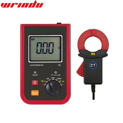
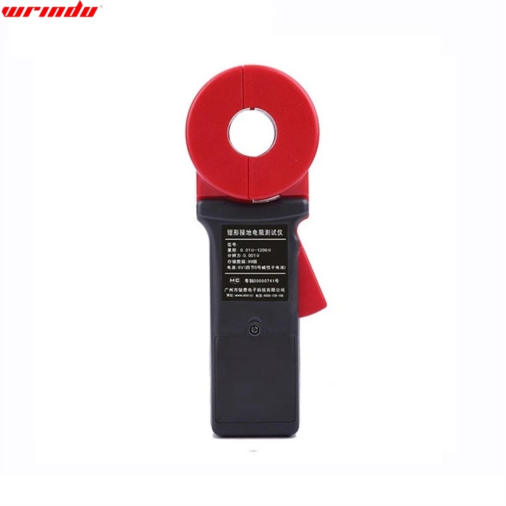
The clamp-on method places a current transformer around the conductor connecting the electrode to the rest of the system and measures the current that circulates. It requires a loop: the current injected by the clamp has to be able to return to the electrode through another earth path.
On a single electrode bonded to a building’s earth system, that loop exists through the building’s other earth connections, and the clamp gives a reading that reflects the resistance of the path it is clamped around. On an isolated electrode, no loop exists and the instrument reports nothing useful.
The quantity measured is therefore the loop resistance, not the resistance of the electrode to remote earth. On a system with many electrodes that are all bonded, the reading is dominated by the parallel combination and by the resistance of the bonding conductors, which makes the method excellent for comparing electrodes against each other and unsuitable for establishing whether a single electrode meets a defined limit. The method’s advantage is that it requires no auxiliary electrodes and can be used in locations where the fall-of-potential method cannot be applied at all.
Soil resistivity context for the result
The resistance of an electrode depends on the resistivity of the soil around it, which is a property of the site rather than of the electrode. Knowing the soil resistivity allows a measured value to be interpreted: a high reading on a dry, sandy site may indicate a perfectly adequate electrode for that soil, while the same reading on a site with conductive soil may indicate a problem.
The resistivity survey is normally performed before the electrode system is designed, using the same instrumentation with four electrodes arranged in a line. The spacing between the electrodes determines the depth to which the measurement is sensitive, so a survey using several spacings produces a picture of how the resistivity changes with depth rather than a single value.
Where a resistivity survey exists, it should be consulted before an earth resistance result is judged against a limit. Where it does not, the measurement of the electrode and the measurement of the soil are two separate exercises, and only one of them can be performed after the installation is complete without disturbing it.
Interference from buried services and rails
Buried metallic services act as parallel earth paths. Current injected during the test divides between the electrode and those paths, and the instrument sees a lower resistance than the electrode alone would present. In a built-up area with a network of water mains, gas mains and cable sheaths, the effect can be substantial.
Railway return currents are the second source of interference. Where a test is performed near a railway, the earth potential between two points is not zero even with no test current applied, and that potential appears as an offset on the measurement. Instruments designed for this environment use a measurement frequency away from the power frequency and its harmonics and apply signal processing to reject the interfering component, which is the reason the test frequency setting matters.
High-voltage installations introduce a third source. Induced voltages from adjacent conductors can be significant, and the test leads should be routed and handled with that in mind. Where induced voltage is present, the reading can be unstable and the instrument may report an error rather than a value.
Reading seasonal variation
Soil resistivity changes with moisture content and temperature, and both vary through the year. Measurements taken in dry summer conditions are typically higher than measurements taken in a wet spring, and the difference can be large enough to move a result across an acceptance limit.
The practical response is to record the season and recent weather with every measurement and to compare like with like. A programme that measures once a year in the same month produces a series that can be trended; a programme that measures when convenient produces a series whose variation reflects the weather rather than the electrode.
Where a measured value is close to the limit, the useful question is what the value would be under the conditions the limit assumes. Many standards specify that the resistance should be verified under the least favourable conditions, and where the measurement is taken at another time, that assumption belongs in the record so the reader knows what the value does and does not cover.
Recording conditions with the measurement
The record should state the method used, the electrode or system under test, and the arrangement of any auxiliary electrodes with their spacing. It should state the test frequency where the instrument allows a choice, the test current, the ambient temperature, the soil condition and the recent weather.
The bonding configuration is part of the record because it determines what the value represents. A measurement taken with the electrode bonded to a large earth system is a measurement of that system, not of the electrode, and a later measurement taken with the bonds removed will not be comparable.
The condition of the connection to the electrode is worth checking before the measurement rather than after an unexpected result. A corroded connection, a test lead attached to a painted surface or a clamp placed around a conductor that is not part of the electrode path all produce values that describe the connection rather than the earth system.
When a method is simply not applicable
A method is not applicable when its precondition is absent. Fall-of-potential cannot be used where there is no room to lay out the auxiliary electrodes. The clamp method cannot be used where there is no loop. Neither can be applied to a system that is energised in a way that makes the test unsafe, and neither produces a valid result when the interference is high enough to dominate the test signal.
Where no method can be applied correctly, the honest outcome is a measurement of a different quantity with its limitation stated, rather than a value presented as an earth resistance. The fallback options are to measure the continuity of the earthing system and its connections, to measure the resistance of a loop within the system, and to verify that the earthing arrangement matches the design.
That distinction matters most in the installations where the measurement is hardest, which are also the installations where the earthing system is most likely to be shared with other services and therefore most likely to change without being documented.
Testing in built-up areas with limited space
In a built-up area the practical approach combines methods rather than choosing one. A clamp measurement establishes the relative condition of each electrode in a bonded system and identifies the ones that differ from the rest. A continuity measurement confirms that the bonding conductors are intact. Where space allows even a limited fall-of-potential arrangement, the measurement can be taken with shorter auxiliary spacings and interpreted with the corresponding reduction in confidence.
The measurements taken together describe a system rather than a single value. That framing is more useful for the question that actually matters in a built-up area, which is whether the earthing system provides a reliable path and whether any part of it has deteriorated, rather than whether one electrode meets a numerical limit.
The requirements for earthing in high-voltage installations are set out in IEC 61936-1, and the corresponding framework for low-voltage installations is in IEC 60364-1. General electrical safety guidance for work of this kind is published by the UK Health and Safety Executive, instrument documentation describing the measurement methods and their arrangements is published by suppliers such as Fluke and Hioki, and the traceability framework that the instrument calibration depends on is described in the NIST handbooks. The instrument range is grouped on the electrical resistance testing hub.
An earth resistance value without the method used to obtain it cannot be compared with anything.
Send the site conditions and an existing result to our engineering team and we will tell you which method the site supports and what the value represents. Earth resistance and resistivity instruments are grouped on the electrical resistance testing hub.
FAQ
Why is the fall-of-potential method preferred where it can be used?
Because it measures the earth electrode system directly rather than inferring it. Current is injected through the electrode and a remote auxiliary electrode, and the potential is measured at a series of positions between them. The shape of the resulting potential profile shows whether the auxiliary electrodes are far enough away, which gives the method a built-in check on its own validity. Its cost is the space required for the auxiliary electrodes and the leads.
When can a clamp-on measurement be used?
When the electrode under test is part of a loop that includes another earth path, because the clamp method works by measuring the current that circulates in that loop. A single electrode connected to nothing else has no loop and cannot be measured this way. On a system with multiple electrodes bonded together, a clamp measurement indicates the combined resistance of the loop, which is useful as a relative comparison between electrodes but is not the same quantity as a fall-of-potential result.
How do buried services affect the measurement?
Metallic services in the ground provide parallel earth paths that carry part of the test current, which lowers the measured value and makes the electrode appear better than it is. Railway return currents and high-voltage earth returns induce voltages in the test leads, which distort the potential measurement. Both effects are strongest in built-up and industrial areas, which is precisely where the alternative methods are most often needed.
Why does the same electrode give different values at different times of year?
Because soil resistivity depends strongly on moisture content and temperature, and both vary seasonally. The earth electrode resistance is determined by the resistivity of the soil around it, so a measurement taken in a dry summer can be significantly higher than one taken in a wet spring. Comparisons between measurements are only meaningful when the season and the recent weather are recorded alongside the value.
What has to be recorded with an earth resistance measurement?
The method used, the electrode or system under test, the spacing of the auxiliary electrodes where the method uses them, the test current or frequency, the soil condition and recent weather, the ambient temperature, and the condition of the connections to the electrode. Where the measurement was taken with the system bonded, the bonding configuration belongs in the record, because it determines what the value represents.
Related articles
 SF6 Leak Detector Sensitivity: Select a Method for the Inspection TaskKnowledge
 Cable Fault Locator Selection for Urban Networks: Routes, Noise and AccessKnowledge
 Substation Battery Load Bank Sizing: Duty, Voltage Range and Heat RejectionKnowledge
 CT Polarity, Ratio and Burden Testing: Find Wiring and Loading ErrorsKnowledge