Wrindu

Power Quality Measurement Equipment

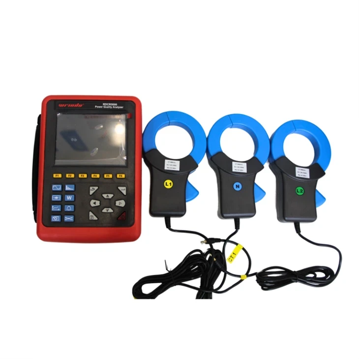
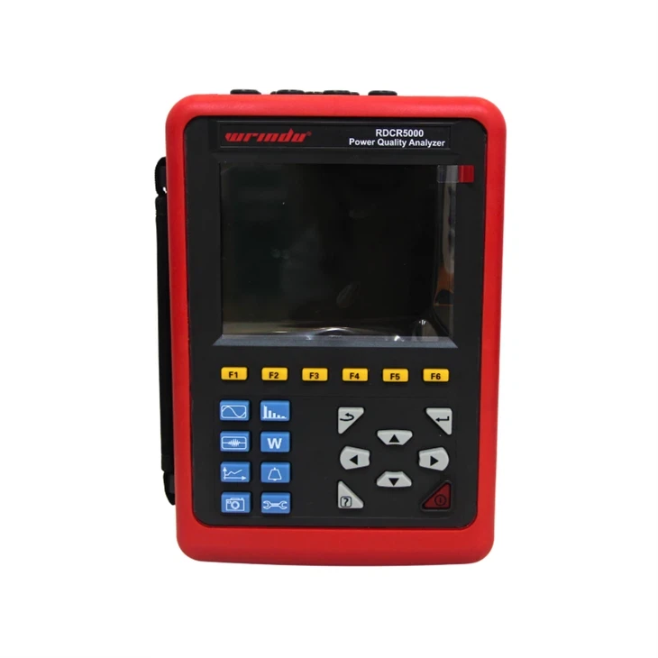
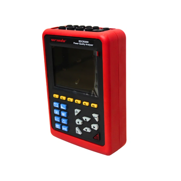
The power quality measurement equipment with high-resolution display, and a durable design. Provides real-time waveforms and harmonic analysis, ensuring comprehensive electrical monitoring and analysis.
Model: RDCR5000

Related Products


OVERVIEW

  • The RDCR5000 power quality measurement equipment is a sophisticated testing device crafted for on-site evaluation of three-phase systems. It’s a versatile and intelligent instrument that simplifies human-machine interaction, ensuring ease of use. The analyzer features a large LCD screen with high resolution, offering clear visuals, and supports both Chinese and English interfaces. Its robust, shock-proof shell is designed to withstand the rigors of fieldwork.


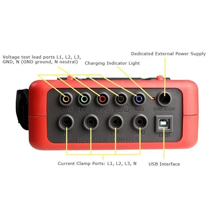
  • The RDCR5000 is capable of simultaneous measurement across four current channels (including ABC phases and neutral current) and four voltage channels (ABC phase voltages and neutral-to-ground voltage). It accurately captures peak current and voltage values, as well as maximum and minimum values over a given period. The power quality measurement equipment assesses three-phase imbalance factors, short-term voltage flicker, transformer K factors, and a range of power parameters including active, reactive, and apparent power, power factor, displacement power factor, and total harmonic distortion.


  • In addition to these measurements, the RDCR5000 displays real-time waveforms and harmonic ratio bar charts for both current and voltage. It can dynamically detect instantaneous changes in voltage and current, monitor starting currents, and keep a watchful eye on power parameters, generating an alarm list and trend charts for long-term recording and analysis of test data.


CHARACTERISTIC


  • 1. The analyzer features a dual-processor architecture with both DSP and ARM chips. The DSP is dedicated to data collection and algorithm processing, while the ARM handles communication protocols and man-machine interface processing.


  • 2. Analog signal acquisition is facilitated by two AD7655 chips from ADI, offering a 16-bit resolution and supporting 4-channel synchronous sampling. The maximum sampling rate of 1 MSPS ensures channel accuracy and data integrity, allowing for precise detection of transient changes in the grid, such as abrupt rises and falls in waveforms and instantaneous interruptions.


  • 3. The DSP operates at a frequency exceeding 200 MHz, enabling real-time monitoring of the power grid and dynamic adjustment of the sampling frequency to achieve synchronization with the power frequency.


  • 4. A 5.6-inch LCD color screen with a resolution of 640 dots x 480 dots is used for display. It can represent parameters such as phase, waveform, vector diagram, and harmonic ratio with different colors, enhancing the efficiency and intuitiveness of understanding the power grid’s state.


  • 5. The built-in flash memory can store up to 60 groups of screenshots, 150 groups of transient voltage/current waveform figures, and 12,800 groups of alarm lists simultaneously. The starting current detection model is capable of continuously capturing the starting current waveform for 100 seconds.


  • 6. An integrated 2G memory card is used to store trend curve records, which can simultaneously record data for 20 parameters (selectable as needed) every five seconds. The trend curve records can be stored for up to 300 days.


APPLICATION

power quality analyzer

1. General Specification

FunctionDescription
Power supplyRechargeable lithium-ion battery packs 9.6V, backup charger.
Battery Level indicatorBattery symbol 5 grid product-76-26 Display power, when the battery level is low, automatically shut down after a 1-minute indication
Working Currentabout 590mA, continuous working 8hours.
Display modeLCD color screen, 640×480, 5.6 inches, display field 116mm × 88mm
Instrument Size240mm×170mm×68 mm.
CT Size008B small sharp current clamp: 7.5mm×13mm; (optional)

040B round jaw current clamp: 35mm×40mm; (optional)

068B round jaw current clamp: 68mm×68mm. (optional)

300F Flexible Coil Current Sensor (with Integrator): Ф300mm (optional)

Number of channels4 voltages, 4 currents
Line Voltage1.0V~2000V.
Phase Voltage1.0V~1000V.
Current008B small sharp current clamp: 10mA~10.0A; (optional)

040B round jaw current clamp: 0.10A~100A; (optional)

068B round jaw current clamp: 1.0A~1000A; (optional)

300F Flexible Coil Current Sensor (with Integrator): 10A ~ 6000A (optional)

Frequency40Hz~70Hz.
Electricity Energy ParameterW, VA, Var, PF, DPF, cosφ, tanφ.
Energy parametersWh, Varh, Vah.
Harmonic WaveYes, 0 – 50 times
Total harmonic distortionYes, 0 – 50 times, each phase
Expert ModeYes.
Transient Record Groups150 groups
Voltage FlickerYes
Start Current ModeYes, 100 seconds
Three-phases UnbalanceYes
Record300 days (record 20 parameters simultaneously, every 5 seconds record 1 point)
Min/Max Recorded ValueYes, the max-min value can be measured for a certain time
Alarm40 different types of parameter selection, 12800 group alarm logs
PeakYes.
Phasor Diagram DisplayAutomatic
Screenshot Capacity60PCS
Menu languageEnglish/Chinese.
Communication InterfaceUSB.
Automatic Shut DownIn the alarm/trend graph recording/transient capture mode (waiting or in progress), the instrument does not automatically shut down
In other test modes, there is no button operation within 15 minutes, prompting to automatically shut down after 1 minute.
Backlight FunctionYes, it is suitable for dark places and nighttime use
Instrument WeightHost: 1.6kg (with battery).
008B small sharp current clamp: 170g×4; (optional)
040B round jaw current clamp: 190g×4; (optional)
068B round jaw current clamp: 510g×4; (optional)
300F Flexible Coil Current Sensor (with Integrator): 330g×4; (optional)
Test wires and power adapter: 900g;
Total weight: about 9.2kg (with package).
Voltage Test Wire Length3m
Current Clamp Wire Length2m
Working Temperature-10°C~40°C; below 80%Rh.
Storage Temperature-10°C~60°C; below 70%Rh.
Input ImpedanceTest voltage input impedance: 1MΩ
Withstand voltageWithstand the sine wave AC voltage of 3700V/50Hz one minute between the instrument line and out shell
InsulationBetween instrument line and shell ≥10MΩ.
StructureDouble insulation, with insulation shock-proof sheath.
SuitableSafely StandardIEC 61010 1000V Cat III / 600V CAT IV, IEC61010-031, IEC61326, Pollution degree: 2.


2. Instrument Accuracy (excluding the current sensor)

Measurement SpecificationRangeDisplay ResolutionMax Error of Reference Range
Frequency40Hz~70Hz0.01Hz±(0.03)Hz
Phase Voltage True RMS1.0V~1000VMin resolution 0.1V±(0.5%+5dgt)
Line Voltage True RMS1.0V~2000VMin resolution 0.1V±(0.5%+5dgt)
DC Voltage1.0V~1000VMin resolution 0.1V±(1.0%+5dgt)
Current True RMS10mA~1000AMin resolution 0.1mA±(0.5%+2dgt)
Phase Voltage Peak1.0V~1414VMin resolution 0.1V±(1.0%+5dgt)
Line Voltage Peak1.0V~2828VMin resolution 0.1V±(1.0%+5dgt)
Current Peak10mA~1414AMin resolution 0.1mA±(1.0%+5dgt)
Peak Factor1.00~3.990.01±(1%+2dgt)
4.00~9.990.01±(5%+2dgt)
Active Power0.000W~9999.9kWMin resolution 0.001W±(1%+3dgt);

Cosφ≥0.8

±(1.5%+10dgt);

0.2≤Cosφ<0.8

Reactive power

Inductive& Capacitive

0.000Var~9999.9kVarMin resolution 0.001Var±(1%+3dgt);Sinφ≥0.5
±(1.5%+10dgt);

0.2≤Sinφ<0.5

Apparent Power0.000VA~9999.9kVAMin resolution 0.001VA± (1%+3dgt %)
Power Factor-1.000~1.0000.001±(1.5%+3dgt);

Cosφ≥0.5

±(1.5%+10dgt);

0.2≤Cosφ<0.5

Active Energy0.000Wh~9999.9MWhMin resolution 0.001Wh±(1%+3dgt);

Cosφ≥0.8

±(1.5%+10dgt);

0.2≤Cosφ<0.8

Reactive Energy

Inductive& Capacitive

0.000Varh~9999.9MVarhMin resolution 0.001Varh±(1%+3dgt);Sinφ≥0.5
±(1.5%+10dgt);

0.2≤Sinφ<0.5

Apparent Energy0.000VAh~9999.9MVAhMin resolution 0.001VAh±(1%+3dgt)
Phase Angle-179°~180°±(2°)
Tanφ(VA≥50VA)-32.768~32.768Min resolution 0.001±(1%+5dgt)
Displacement Power Factor(DPF)-1.000~1.0000.001±(1%+5dgt)
HarmonicRatio

(Vrms>50V)

0.0 %~99.9 %0.1 %±(1%+5dgt)
Harmonic

Angle(Vrms >50V)

-179°~180°±(3°)harmonic1~25
±(10°)harmonic26~50
Total Harmonic Rate

(DF or THD-F)≤50

0.0 %~99.9 %0.1 %±(1%+5dgt)
Distortion Factor

(DF or THD-R)≤50

0.0 %~99.9 %0.1 %±(1%+10dgt)
Transformer

K Factor

1.00~99.990.01±(5 %)
Three-phase Unbalance0.0%~100 %0.1 %±(1 %)

Note: The following data are presented in reference conditions and ideal current sensors (completely linear and without phase displacement).


3. Current Sensor Characteristics (Optional)

Current sensor modelCurrent ClampCurrent True RMSCurrent True RMS Max ErrorPhase Angle φ Max Error
008B

small sharp current clamp: 7.5mm×13mm

product-110-3410mA~99mA±(1%rdg+3dgt)±(1.5°),Arms≥20mA
100mA~10.0A±(1%rdg+3dgt)±(1°)
040B

round jaw current clamp:Ф40mm

product-102-480.10A~0.99A±(1%rdg+3dgt)±(1.5°)
1.00A~100A±(1%rdg+3dgt)±(1°)
068B

round jaw current clamp:Ф68mm

product-110-501.0A~9.9A±(2%rdg+3dgt)±(3°)
10.0A~1000A±(2%rdg+3dgt)±(2°)
300F

Flexible Coil Current Sensor:Ф300mm

product-110-5010A~99A±(1%rdg+3dgt)±(3°)
100A~6000A±(1%rdg+3dgt)±(2°)

Note: the above four current sensors are selected by users according to their own needs. (If not, select R068B round jaw current clamp by default)


Send Inquiry