
Transformer Testing Safety: Isolation, Discharge and Work Practice
Send your test requirement — get a tailored solution and a quote within one working day.
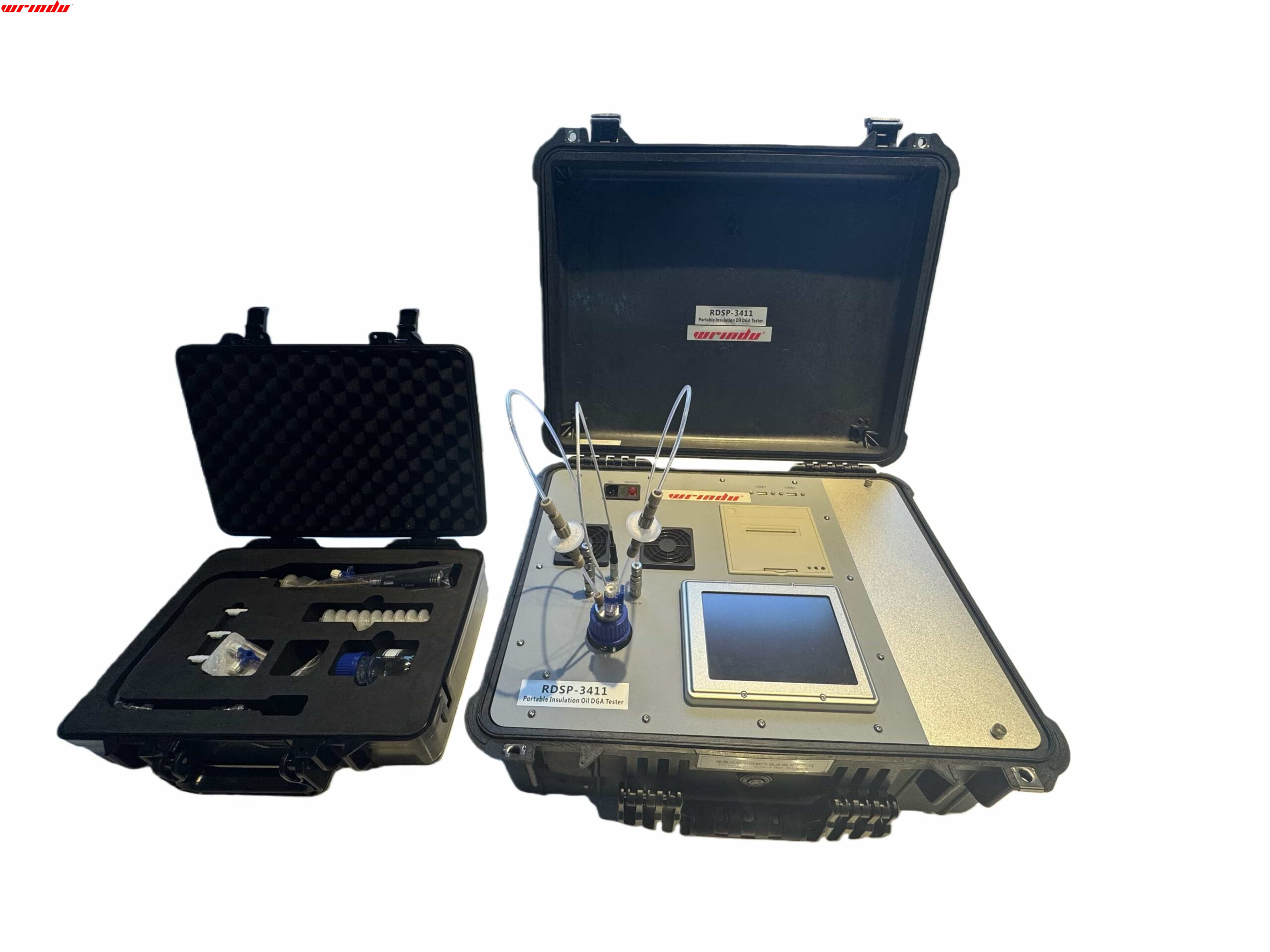
Safe transformer testing is built on a discipline that never varies: isolate the transformer and verify zero energy, discharge stored energy before touching anything, re-verify after the discharge, and control the area and the people around it. Test procedures change from one measurement to the next, but this safety chain does not.
The rules below apply across insulation resistance, winding resistance, ratio, excitation and diagnostic testing, and they must be followed together with the specific procedure, the manufacturer instructions and the site safety rules that apply to your work.
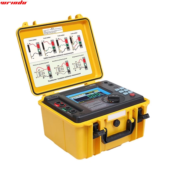
The Safety Chain Before Any Transformer Test
The safety chain has five links: isolation, zero-energy verification, discharge, re-verification, and grounding and area control. Removing any link breaks the chain. A transformer that has been disconnected from the system is not automatically safe to test: its windings can hold capacitive charge, its core can retain residual effects from earlier DC testing, and its bushings can accumulate charge from atmospheric effects. The chain exists because the transformer, not the tester, decides what energy is present. Work through the links in order and in writing. The person performing the test should be able to state, for each connection they touch, why it is safe at that moment. If that statement cannot be made, the work stops until it can.
Isolation, Lockout and Zero-Energy Verification
Isolation means more than opening a switch. The transformer must be disconnected from every possible source of energy: the high-voltage and low-voltage circuits, the neutral where applicable, auxiliary supplies and any connected equipment that could back-feed the winding. Lockout and tagout procedures then prevent someone from restoring the supply while the test team is connected. A written isolation plan and a clear handover between operators and testers are part of the same step. Zero-energy verification is not a glance at a switch position. Use a suitable voltage detector to confirm that no voltage is present on every terminal that will be touched, and confirm the detector works before and after the check. On large transformers, capacitive coupling from adjacent energized plant can hold a voltage on an isolated winding, so the verification must be done at the terminals, not at the disconnecting point.Discharge: How Long Is Long Enough in Practice
Discharge is where fixed rules fail, because the stored energy depends on the transformer, the test that was performed and the conditions. A winding resistance test at high current leaves magnetic energy in the core; an insulation resistance test at high DC voltage leaves charge on the winding capacitance; a large transformer can hold that charge for a surprisingly long time. The only defensible answer to “how long is long enough” is: long enough for the voltage to collapse, and long enough is verified by measurement, not assumed. Use the tester’s discharge function where available, then verify with a voltmeter that the voltage has fallen to a safe level before the ground is removed and connections are touched. Some modern testers discharge automatically and indicate when the winding is safe, but the indication should be confirmed rather than trusted blindly. If the voltage is still present, wait, discharge again, and find out why the first discharge did not complete before proceeding.Re-Verification, Grounding and Keeping the Circuit Safe
After discharge, ground the winding to keep it safe while connections are made and changed. Temporary grounding provides a controlled path for any charge that reappears, for example from capacitive coupling while other work continues nearby. The ground must be visible, deliberate and removed in a controlled sequence before the transformer is returned to service; a forgotten temporary ground is a common cause of energization incidents. Re-verify at every change of connection. Between two measurements on the same transformer, the configuration of the test leads changes, and each change is an opportunity to touch something that was not discharged. The rhythm of the work should be: change connection, verify, test, discharge, verify, change connection.
Area Control, Communication and Test Team Roles
Test area control protects people who are not part of the test team. Define the boundary of the test area, put up warning signs, and control access while high-voltage test equipment is in use. On large units, the transformer itself, the test set and the cable runs between them are all part of the hazard zone, and the boundary must account for the whole circuit, not just the terminals. Communication rules prevent the classic accidents: someone restoring the supply while the test is running, someone touching a connection believing the test has finished, or someone starting the next measurement while another person is still at the terminals. Agree the start and stop signals before the test, assign one person the authority to start and stop the voltage, and make sure every member of the team knows who that person is. If a test set is remotely controlled, agree who operates the remote and how the operator confirms that the area is clear before energizing. Plan for the unexpected before it happens. Decide in advance what the team does if a tester alarms during a measurement, if a voltage detector indicates a voltage that should not be there, or if someone needs to enter the test area mid-test. The response to an alarm should never be “let me check the terminals”; it should be: stop the voltage, secure the area, discharge and verify, then investigate. If a second person is needed for the investigation, the communication rules still apply, and the person who stopped the test retains authority until the circuit is verified safe again. These pre-agreed responses matter most at the end of a long day, when familiarity is highest and attention is lowest. The discipline of stopping, securing and verifying is what keeps an unusual event from becoming an injury, and it costs nothing to rehearse before the first test of the morning.Safety Do’s and Don’ts Checklist
| Do | Don’t |
|---|---|
| Isolate and lock out every energy source, then verify zero energy at the terminals. | Don’t rely on a switch position or a breaker label alone. |
| Discharge after every DC test and verify with a voltmeter. | Don’t assume a fixed discharge time applies to every transformer. |
| Ground the winding between connection changes and remove temporary grounds in a controlled sequence. | Don’t leave temporary grounds in place for energization. |
| Control the test area, sign the boundary, and agree start/stop authority. | Don’t energize while anyone is near the terminals or cable runs. |
| Follow the specific test procedure, OEM instructions and site rules together. | Don’t let a single “safe looking” reading shorten the procedure. |
Frequently Asked Questions
Why must a winding be discharged after an insulation test?
An insulation resistance test applies a DC voltage that charges the winding capacitance. When the tester is disconnected, that charge remains and can deliver a dangerous shock. The winding must be discharged and the voltage verified at the terminals before connections are touched.What is lockout/tagout in transformer testing?
Lockout and tagout is the procedure used to isolate the transformer from every energy source and prevent restoration while work is in progress. Each person working on the equipment applies their own lock and tag, and removal is controlled so that no one can re-energize the circuit before the test team is clear.How do I verify zero energy before touching a transformer?
Use a voltage detector that is proven to work before and after the check, and test at the terminals themselves rather than at the disconnecting point. On large units, verify again after any change of connection, because capacitive coupling from adjacent plant can re-establish a voltage on an isolated winding. The instruments used in transformer maintenance testing are listed on the transformer maintenance test equipment page, and the full lifecycle test programme is described in What Tests Are Required for a Power Transformer.Related articles
 SF6 Leak Detector Sensitivity: Select a Method for the Inspection TaskKnowledge
 Cable Fault Locator Selection for Urban Networks: Routes, Noise and AccessKnowledge
 Substation Battery Load Bank Sizing: Duty, Voltage Range and Heat RejectionKnowledge
 CT Polarity, Ratio and Burden Testing: Find Wiring and Loading ErrorsKnowledge