
OLTC Transition Resistor Testing: Compare Measurements with the Tap Changer Design
Send your test requirement — get a tailored solution and a quote within one working day.
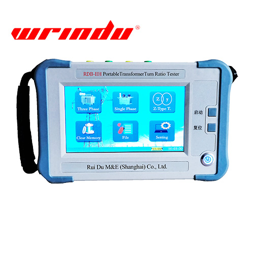
OLTC Transition Resistor Testing requires evidence that a field, laboratory and procurement team can reconstruct. The working angle is to own transition-resistor evidence and OEM-dependent interpretation, distinct from DRM waveform classification. This guide is for Utility, EPC, commissioning, maintenance or test-laboratory engineers; procurement and protection teams where applicable at the field test / diagnosis stage. It controls the test boundary, raw record and conclusion. Acceptance values and model capability must still come from the approved asset procedure, applicable standard edition and current manufacturer documentation.
OLTC Transition Resistor Testing: Which resistor and transition design is being assessed?
Use the approved design reference to identify it.
Use method-specific evidence and a controlled repeat; one reading cannot establish equipment condition when connections, operating state, environmental conditions or measurement settings remain uncertain during field testing.
Treat the work under “OLTC Transition Resistor Testing: Which resistor and transition design is being assessed” as controlled decisions, not one instrument reading. Start with the power transformer, its core, winding, tap position and terminal configuration. Document connection diagram, tap position, grounding state, test current or excitation, temperature and residual magnetism, plus the intended observation, comparison source and stop conditions before energization or capture.
For “OLTC Transition Resistor Testing: Which resistor and transition design is being assessed” in OLTC transition resistor testing, preserve applied quantity, measured quantity, phase and tap identifiers, stabilization behavior, raw repeat values and instrument identification, then review them using a controlled repeat plus the relevant ratio, winding-resistance, excitation, SFRA, insulation or drawing evidence. If they do not support the intended decision, narrow the conclusion and specify a repeat or complementary method.
For the scope and terminology used in “OLTC Transition Resistor Testing: Which resistor and transition design is being assessed,” consult IEC 60076-1 power transformer scope and confirm the contractually applicable edition. The approved project procedure still controls acceptance.
Read the tap-changer diagram and OEM test basis
For “Read the tap-changer diagram and OEM test basis,” define the OLTC transition resistor testing boundary before connection or data capture. State the asset condition, intended observation, comparison source and stop condition.
Under “Read the tap-changer diagram and OEM test basis,” preserve applied quantity, measured quantity, phase and tap identifiers, stabilization behavior, raw repeat values and instrument identification. Compare equivalent records and investigate a setup, connection or magnetization effect before assigning the observation to asset condition.
For “Read the tap-changer diagram and OEM test basis,” use IEC 60076-3 insulation-level and dielectric-test scope for scope and terminology; the approved project procedure controls acceptance. See Wrindu’s related technical owner page, then verify model capability in the current manual.
Define access and isolation responsibilities
For “Define access and isolation responsibilities,” define the OLTC transition resistor testing boundary before connection or data capture. State the asset condition, intended observation, comparison source and stop condition.
Under “Define access and isolation responsibilities,” use a controlled repeat plus the relevant ratio, winding-resistance, excitation, SFRA, insulation or drawing evidence. If the evidence conflicts, narrow the conclusion, identify the unresolved condition and assign a controlled repeat.
For “Define access and isolation responsibilities,” use IEC 60076-18 frequency-response measurement scope for scope and terminology; the approved project procedure controls acceptance.
Why are static resistor values different from DRM evidence?
Because the measurement changes with test context.
Hold the test boundary constant, preserve raw data and verify the reference basis before the result is accepted, trended, reported or used to direct further work.
For “Why are static resistor values different from DRM evidence,” state what changed and what remained controlled. Compare applied quantity, measured quantity, phase and tap identifiers, stabilization behavior, raw repeat values and instrument identification with the approved reference, and describe the observation as bounded evidence rather than a complete diagnosis.
For “Why are static resistor values different from DRM evidence” in OLTC transition resistor testing, challenge the first explanation with a controlled repeat plus the relevant ratio, winding-resistance, excitation, SFRA, insulation or drawing evidence. Keep findings separate when methods address different quantities; this limits an unsupported winding or core diagnosis.
For the scope and terminology used in “Why are static resistor values different from DRM evidence,” consult IEC 60076-21 transformer test-code scope and confirm the contractually applicable edition. The approved project procedure still controls acceptance. See Wrindu’s power transformer testing hub, then verify model capability in the current manual.
Check temperature and measurement path comparability
For “Check temperature and measurement path comparability,” define the OLTC transition resistor testing boundary before connection or data capture. State the asset condition, intended observation, comparison source and stop condition.
Under “Check temperature and measurement path comparability,” preserve applied quantity, measured quantity, phase and tap identifiers, stabilization behavior, raw repeat values and instrument identification. Compare equivalent records and investigate a setup, connection or magnetization effect before assigning the observation to asset condition.
For “Check temperature and measurement path comparability,” use NIST measurement uncertainty guidance for scope and terminology; the approved project procedure controls acceptance.
| Resistor identity | design value source | temperature | measured path | result | disposition |
|---|---|---|---|---|---|
| Record resistor identity with its source. | Record design value source with its source. | Record temperature with its source. | Record measured path with its source. | Record result with its source. | Record disposition with its source. |
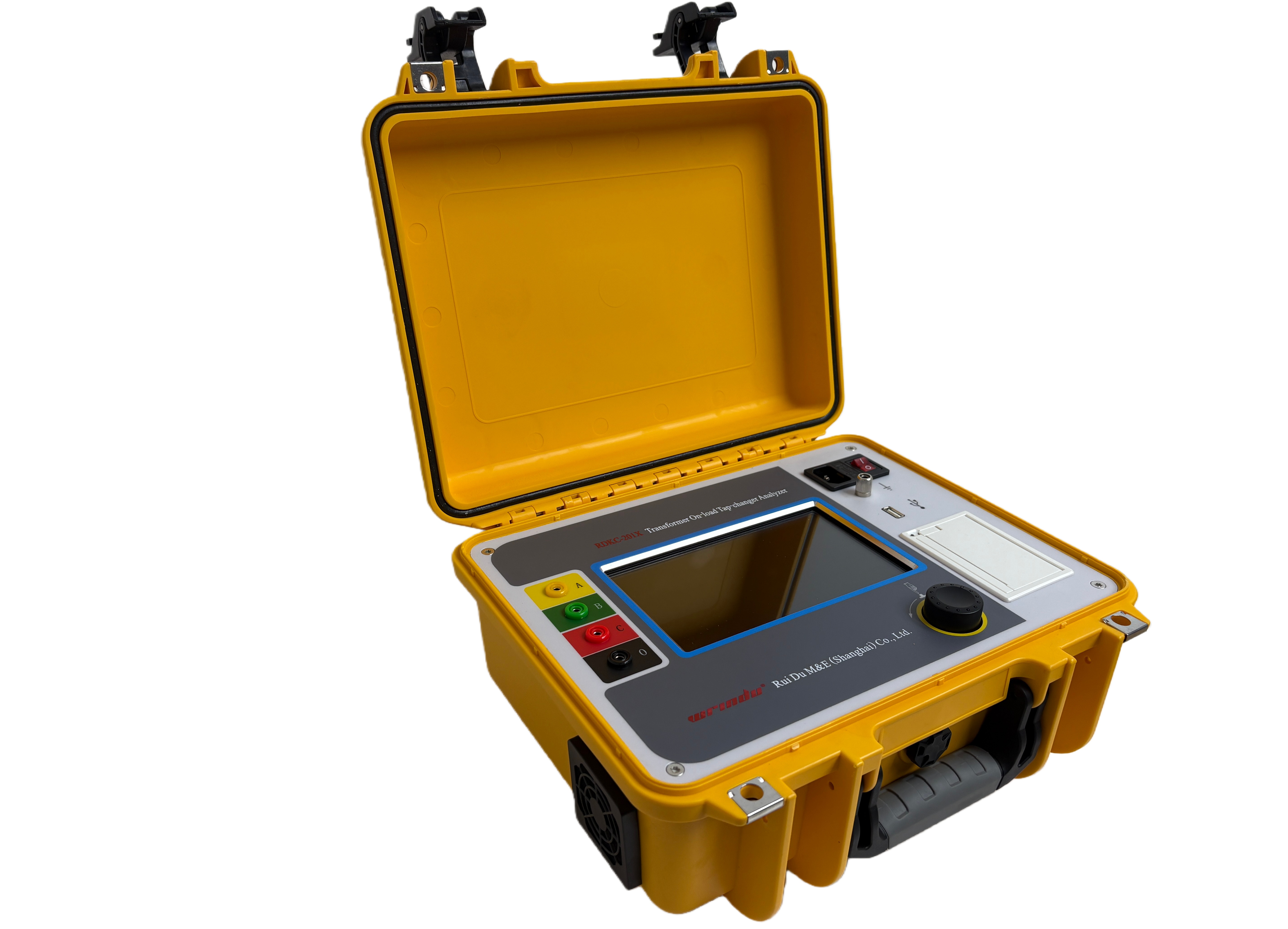
Compare positions only where the design permits
For “Compare positions only where the design permits,” define the OLTC transition resistor testing boundary before connection or data capture. State the asset condition, intended observation, comparison source and stop condition.
Under “Compare positions only where the design permits,” use a controlled repeat plus the relevant ratio, winding-resistance, excitation, SFRA, insulation or drawing evidence. If the evidence conflicts, narrow the conclusion, identify the unresolved condition and assign a controlled repeat.
For “Compare positions only where the design permits,” record the governing standard, utility rule and manufacturer instruction before freezing acceptance criteria.
Escalate a deviation with supporting waveform evidence
For “Escalate a deviation with supporting waveform evidence,” define the OLTC transition resistor testing boundary before connection or data capture. State the asset condition, intended observation, comparison source and stop condition.
Under “Escalate a deviation with supporting waveform evidence,” record connection diagram, tap position, grounding state, test current or excitation, temperature and residual magnetism. A setup change creates a new comparison case, so do not merge its values with the original trend.
For “Escalate a deviation with supporting waveform evidence,” record the governing standard, utility rule and manufacturer instruction before freezing acceptance criteria.
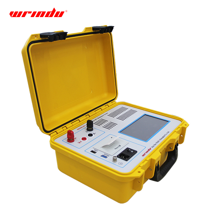
Restore connections and file the resistor test record
For “Restore connections and file the resistor test record,” define the OLTC transition resistor testing boundary before connection or data capture. State the asset condition, intended observation, comparison source and stop condition.
Under “Restore connections and file the resistor test record,” preserve applied quantity, measured quantity, phase and tap identifiers, stabilization behavior, raw repeat values and instrument identification. Compare equivalent records and investigate a setup, connection or magnetization effect before assigning the observation to asset condition.
For “Restore connections and file the resistor test record,” record the governing standard, utility rule and manufacturer instruction before freezing acceptance criteria.
A defensible OLTC transition resistor testing decision rests on a controlled setup, raw records and an explicit comparison basis. Separate observation from interpretation, identify unresolved conditions and assign each next action. When evidence is incomplete, use a controlled repeat or complementary method and leave asset acceptance with the responsible engineering authority.
FAQ
What evidence should be recorded when assessing OLTC transition resistor testing?
For OLTC transition resistor testing, confirm connection diagram, tap position, grounding state, test current or excitation, temperature and residual magnetism before comparing results. Preserve applied quantity, measured quantity, phase and tap identifiers, stabilization behavior, raw repeat values and instrument identification. Identify every missing reference or uncontrolled condition, verify the applicable standard and instrument manual, and record the limitation plus its action owner. An incomplete observation should remain an open engineering question, not become an acceptance decision.
Which conditions can make OLTC transition resistor testing results difficult to compare?
The answer depends on the verified asset and method boundary. For OLTC transition resistor testing, use a controlled repeat plus the relevant ratio, winding-resistance, excitation, SFRA, insulation or drawing evidence and retain the raw record. Never transfer a criterion from another configuration or test stage without written authority. If the evidence remains inconsistent, repeat the controlled test portion or refer the bounded issue for engineering review.
When should an inconclusive OLTC transition resistor testing result be escalated?
For OLTC transition resistor testing, identify the decision owner and governing procedure first. Check connection diagram, tap position, grounding state, test current or excitation, temperature and residual magnetism, then compare saved data with a valid reference. Request missing capability, calibration or method evidence before relying on the result. The final record must separate what was established, what remains uncertain and which assigned action closes the issue.
Review the OLTC transition resistor testing scope
Send the asset, objective, governing procedure, required range, accessories and reporting format. Wrindu can review an instrument configuration; the responsible engineering team retains the acceptance decision.
{“@context”:”https://schema.org”,”@type”:”FAQPage”,”mainEntity”:[{“@type”:”Question”,”name”:”What evidence should be recorded when assessing OLTC transition resistor testing?”,”acceptedAnswer”:{“@type”:”Answer”,”text”:”For OLTC transition resistor testing, confirm connection diagram, tap position, grounding state, test current or excitation, temperature and residual magnetism before comparing results. Preserve applied quantity, measured quantity, phase and tap identifiers, stabilization behavior, raw repeat values and instrument identification. Identify every missing reference or uncontrolled condition, verify the applicable standard and instrument manual, and record the limitation plus its action owner. An incomplete observation should remain an open engineering question, not become an acceptance decision.”}},{“@type”:”Question”,”name”:”Which conditions can make OLTC transition resistor testing results difficult to compare?”,”acceptedAnswer”:{“@type”:”Answer”,”text”:”The answer depends on the verified asset and method boundary. For OLTC transition resistor testing, use a controlled repeat plus the relevant ratio, winding-resistance, excitation, SFRA, insulation or drawing evidence and retain the raw record. Never transfer a criterion from another configuration or test stage without written authority. If the evidence remains inconsistent, repeat the controlled test portion or refer the bounded issue for engineering review.”}},{“@type”:”Question”,”name”:”When should an inconclusive OLTC transition resistor testing result be escalated?”,”acceptedAnswer”:{“@type”:”Answer”,”text”:”For OLTC transition resistor testing, identify the decision owner and governing procedure first. Check connection diagram, tap position, grounding state, test current or excitation, temperature and residual magnetism, then compare saved data with a valid reference. Request missing capability, calibration or method evidence before relying on the result. The final record must separate what was established, what remains uncertain and which assigned action closes the issue.”}}]}
Related articles
 Transformer Winding Resistance Test Current Selection: Balance Stabilization and HeatingTransformer test diagnosticsTransformer Magnetic Balance Test: Interpret Phase Patterns with Connection ContextTransformer test diagnosticsTransformer Shorted Turns Diagnosis: Combine Evidence Before Rejecting a WindingTransformer test diagnosticsTransformer Zero Sequence Impedance Test: Specify the Connection and Report BasisTransformer test diagnostics