
10 kV vs 12 kV Tan Delta Test Set: How Should Buyers Choose?
Send your test requirement — get a tailored solution and a quote within one working day.
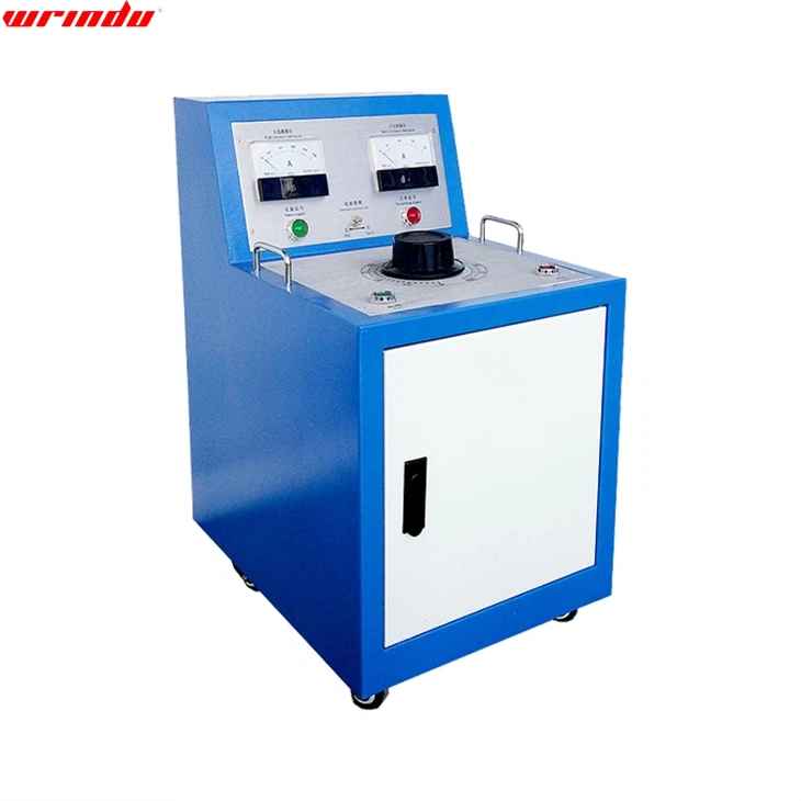
Choose between a 10 kV and a 12 kV tan delta test set by matching the required test voltage to your assets and applicable procedures, not by preferring the higher number. The useful comparison is output power at the rated voltage, capacitive load capability, duty cycle, interference suppression, connection modes, calibration and reporting, because a higher maximum voltage without the power to drive the load adds no value.
The table shows the decision structure, not a model ranking. Confirm every cell with the supplier’s documented specification before comparing quotes.
When the responses arrive, compare them against the same asset list and the same procedure list, not against each other in the abstract. Add the total cost of ownership items: calibration service, training, spare leads and software updates, because these recurring costs can outweigh the difference between the two voltage ratings over the set’s service life.
Start with the Required Test Voltage and Applicable Procedure
The test voltage is defined by the asset and the procedure you must follow. Different insulation systems, voltage classes and test standards call for different test voltages, and the set must deliver the required voltage at the capacitance of the test object. List the assets in your programme, their capacitance values and the test voltages required by the applicable standards or client specifications before comparing the two voltage ratings. If your programme never requires 12 kV, a 12 kV maximum rating is irrelevant to the selection. If a future project requires it, the comparison shifts to whether the set can deliver that voltage at the expected load and duty cycle, which is a power question, not a label question. Also separate the test set’s voltage rating from the test voltage used for each asset. A 12 kV set is often operated at 10 kV or lower when the procedure calls for it, and the specification must state the output capability across the operating range, not only at the maximum. Buyers should ask for the delivered voltage and load curves rather than the marketing headline. The asset mix decides the voltage requirement: winding insulation tests, bushing C1 measurements and different voltage classes each call for test voltages defined by the applicable procedure. List the procedures by asset and extract the required test voltage from each, so the specification is derived from the programme rather than from a preference for a higher number.Compare Output Power, Capacitance Load and Duty Cycle
A tan delta test set must supply the reactive current the test object draws at the test voltage, which grows with frequency and capacitance. The rated output power at the test voltage determines the maximum capacitance the set can drive. Two sets with the same voltage rating can differ significantly in the capacitance they can measure reliably, and exceeding the rating produces unstable or invalid readings. Duty cycle matters for field programmes that test many bushings or winding sections in one day. Compare the continuous or intermittent duty rating, the cooling behaviour and the time the set needs between measurements. A set that meets the voltage but overheats after two measurements does not fit a full-day substation programme. The relationship between voltage, frequency, capacitance and current explains why load matters: the charging current is proportional to frequency times capacitance times voltage, so a test object with large capacitance draws a significant current at the rated voltage. The set must supply that current within its output and thermal limits. If the datasheet lists maximum capacitance at the test voltage, use it to check every asset in your programme. Ask the supplier to state the maximum capacitance at each test voltage and the corresponding duty cycle in the same table, because the two figures together define the practical throughput. A set that lists a high capacitance rating only at a low voltage or with a long cooldown between measurements is less capable in the field than its headline suggests.Interference Suppression for Energised Substation Environments
Field tan delta measurements near energised equipment are corrupted by electromagnetic interference, which shows up as unstable or offset readings. Evaluate the set’s interference suppression: automatic interference cancellation, shielded and guarded test leads, and the ability to reject noise at the test frequency. The difference between a 10 kV and 12 kV set is secondary to this capability in a substation environment. Ask the supplier how the instrument behaves when the interference current is comparable to the measurement current, and request field references or a demonstration if possible. An instrument that produces stable readings in a live substation bay is worth more than a higher voltage rating that is never used in that environment. Interference handling also depends on the operator’s grounding discipline. The instrument’s ground reference, the test object’s ground connection and the lead screens form the rejection path, so the specification should describe the grounding arrangement the instrument expects and the training the supplier provides for it.UST, GST and GSTg Connection Capability
Verify that the set supports the connection modes your assets require: UST for ungrounded specimens, GST for grounded specimens and GSTg for guarded grounded-specimen measurements. Transformer and bushing assessments routinely need all three to separate insulation sections, so a set limited to one or two modes constrains your test programme. Also check the number of terminals and the quality of the guard implementation. The guard must be continuous, well-insulated and able to exclude the intended section cleanly, because the mode capability is only as good as the connection hardware and software that implement it. Confirm that the set can store and report the mode for every measurement, because the trend record is only interpretable when each reading carries its connection mode and test voltage. A set that forgets the mode in its report forces manual reconstruction later and invites comparison errors.Calibration, Safety Interlocks and Reporting Software
Calibration traceability is the foundation of any comparison: ask for the calibration standard, the reported accuracy at the test voltages you will use, and the calibration interval. A set with excellent specifications and no traceable calibration cannot support acceptance or maintenance decisions. Safety interlocks should cover high-voltage output, discharge before lead removal, and interlock with the test object’s grounding state. Reporting software should produce the traceability fields your clients require: asset identification, test mode, voltage, temperature, capacitance, tan delta, calibration data and the operator. These features determine whether the field results become audit-ready records without manual transcription. Calibration should be verified at the voltages you will actually use. An accuracy statement at one voltage does not guarantee the same accuracy across the range, so ask for the accuracy table at 10 kV and 12 kV and for the calibration certificate that supports it. If the supplier cannot provide this, the set cannot support the acceptance evidence your programme may require. Also confirm the set’s safety certification status and the interlock behaviour during discharge, because a high-voltage source without verified interlocks is a hazard regardless of its measurement performance.Questions Buyers Should Put in the Technical Specification
Write the specification around the assets and procedures, not the voltage label. Require the supplier to state the maximum capacitive load at each test voltage, the duty cycle, the interference suppression method and its limits, the supported connection modes, the accuracy with calibration traceability, the safety interlock list and the reporting format. Add the temperature and humidity range for field use and the transport requirements.| Selection factor | 10 kV set | 12 kV set | What to verify |
|---|---|---|---|
| Maximum test voltage | 10 kV | 12 kV | Is the extra voltage required by any of your procedures? |
| Output at rated voltage | Varies by model | Varies by model | Maximum capacitance load at the voltage you will actually use |
| Duty cycle | Varies by model | Varies by model | Continuous testing throughput for a full-day programme |
| Connection modes | UST/GST/GSTg as configured | UST/GST/GSTg as configured | Mode support is a configuration feature, not a voltage feature |
Frequently Asked Questions
Is a higher test voltage always better?
No. The test voltage must match the asset and the applicable procedure. A higher maximum voltage without the output power to drive the test object, or without a procedure that requires it, adds cost and risk without adding evidence.What does output power mean for a tan delta set?
Output power determines the maximum capacitive load the set can drive at the rated voltage. At a given voltage and frequency, the current grows with capacitance, so the power rating defines how large a test object the set can measure reliably.Why is interference suppression important?
Because field measurements near energised equipment can be corrupted by external interference, producing unstable or offset tan delta values. Automatic interference cancellation and guarded, shielded leads keep the measurement valid where it matters most, in the substation. For the framework that decides when and how to use tan delta testing, see the tan delta testing guide. To compare 10 kV and 12 kV test set configurations against your asset list, review tan delta test set options and request a technical proposal.Related articles
 SF6 Leak Detector Sensitivity: Select a Method for the Inspection TaskKnowledge
 Cable Fault Locator Selection for Urban Networks: Routes, Noise and AccessKnowledge
 Substation Battery Load Bank Sizing: Duty, Voltage Range and Heat RejectionKnowledge
 CT Polarity, Ratio and Burden Testing: Find Wiring and Loading ErrorsKnowledge